Week 8- Moving zones approach in Fluent
1) The approaches by which we would model moving zones are
- Moving reference frame
- Moving mesh approach.
We also have few models under moving reference frame
- Single Reference Frame model (SRF)
- Multiple Reference Frame model (MRF)
- Mixing Plane Model (MPM)
- Sliding Mesh Model
2) To model unsteady phenomena we use moving mesh approach.
3)
Aim
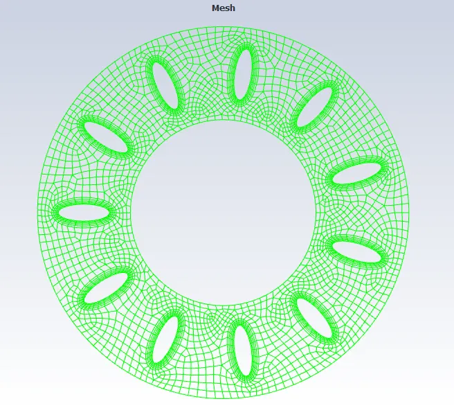
To simulate rotary motion for the the given 2D impeller.
Mesh
Models used
Solver - Pressure based
Velocity formulation - Absolute
Time - Steady
2D space - Plannar
Viscous - k-Epsilon - Realizable - Enhanced wall treatment.
Results
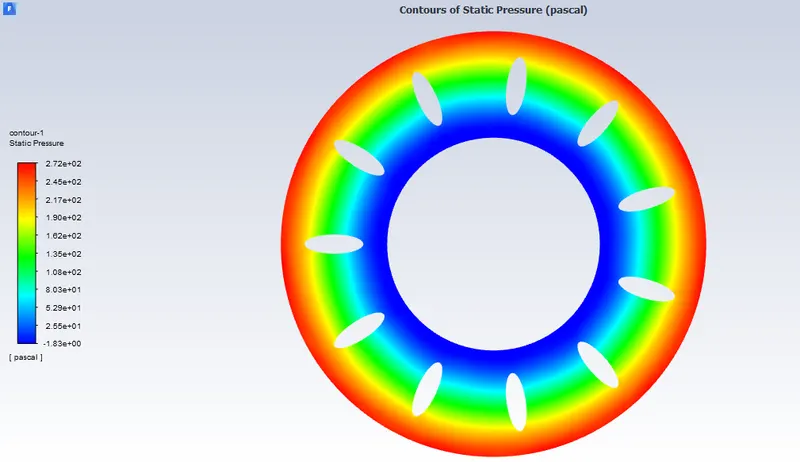
Static pressure contour plot
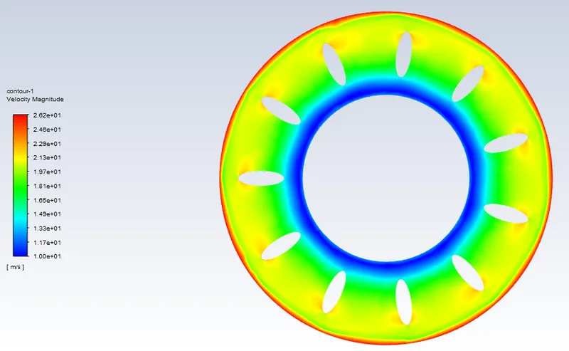
Velocity contour plot
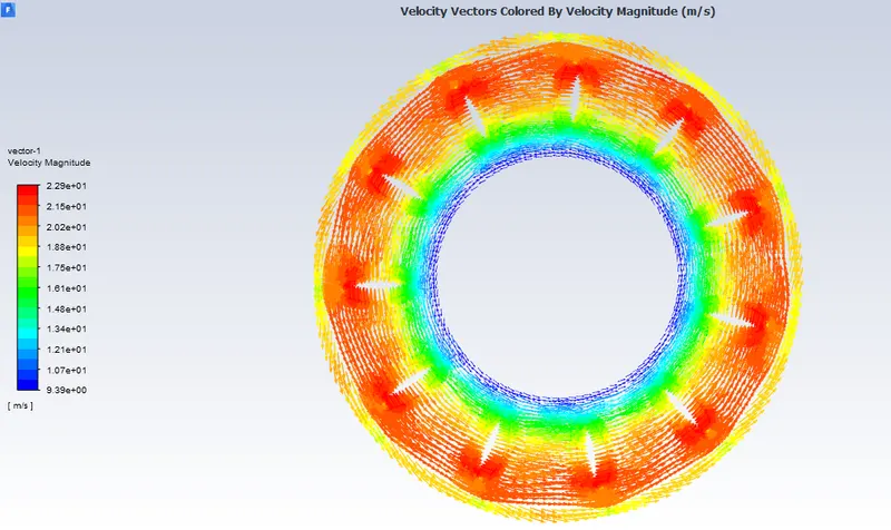
Vector contour plot
Conclusion
If you see the static pressure contour plot there is low pressure region at the center of the impeller, this is because the suction af air takes place there. In the velocity contour towards the trailing edge of the airfoil the velocity increases till the maximum diameter of the impeller.