Week - 8 - Morphing
Objectives:
) Practice all the Morphing techniques that were shown in the video for Model-1.
2) Perform morphing for the Model-2 and Increase the Height of the Dog houses and Ribs.
Morphing: It is a method of changing the design or shape of the component without any numerical input.
Applications of morphing:
- In aero engine widely used in wing design, rotor blade angle.
- In CFD such as the design of the outlet pipe in turbomachines.
- Other fields like marine, power train, biomechanics etc.
Types of morphing:
- Box morphing: Domain morphing is performed via boxed that is created around a particular part or assembly that the user intends to morph. The movement of the morphing box control points define the morphing operation on the entities inside the morphed box. This type of morphing can be applied to both FE and geometry-based models.
- Direct morphing: ANSA direct morphing gives the user the ability to efficiently modify a part locally without having to create morphed boxes. This is extremely useful to create local modification on a single part. Creation of depressions, surface fitting, moving selected parts along a contour surface, and also ability to freeze during morphing process are some of the direct morphing abilities.
- Parametric morphing: The desired morphing actions can be saved as parameters that can be accessed in batch mode. Users can enforce direct shape change by changing directly the numerical input value for appropriate parameters. This morphing method can be coupled by morphing operation to external optimizer. The scripting capability of ANSA can help deliver faster DOE models.
- Geometry morphing: This pioneering concept allows the user to utilize the inventory of all familiar FE morphing operation in a CAD environment.
Model 1
Import the CAD model by using file>> choose open option.
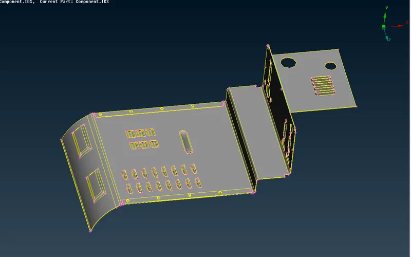
fig 1
After importing CAD model switch to morph module.
Go to boxes >> new>> ortho option and select the FE entity and set geometry and box types as ortho and create a box.
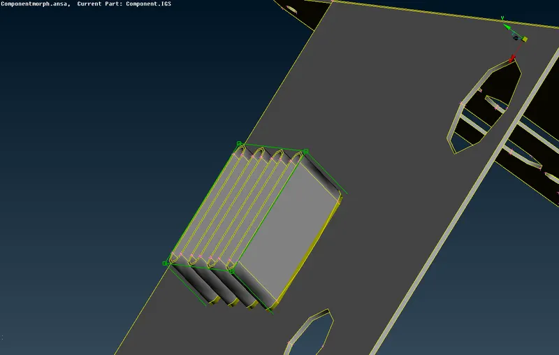
fig. 2
Go to box morphing >> move option>> select the box and move accordingly.
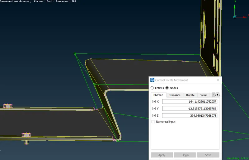
fig 3
After adjusting the geometry, middle click on the mouse to change the shape of geometry.
The final morphed shape.
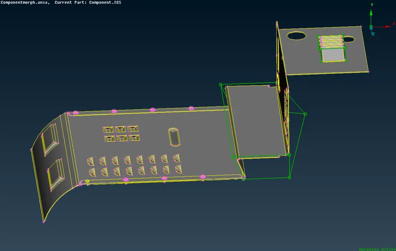
fig 4
Model 2
Import the CAD model by using file>> choose open option.
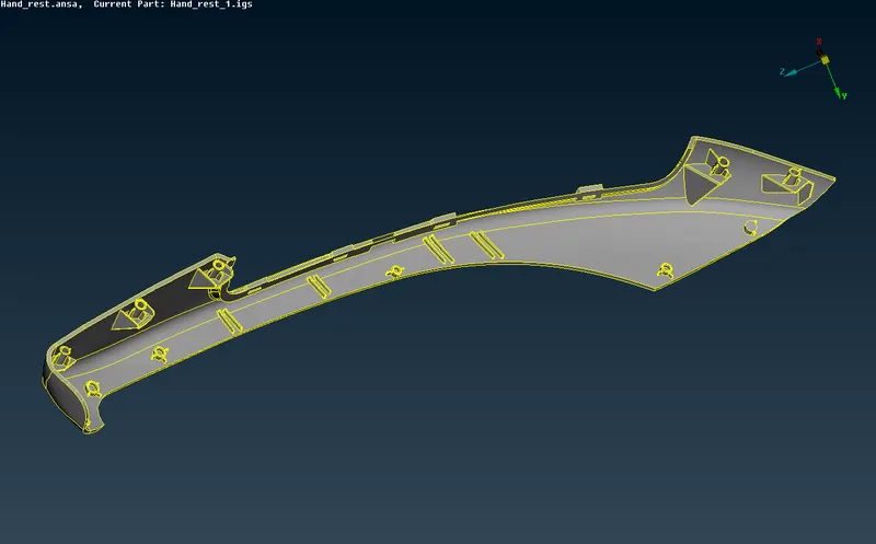
fig 5
After importing CAD model switch to morph module.
Go to boxes >> new>> ortho option and select the FE entity and set geometry and box types as ortho and create a box.
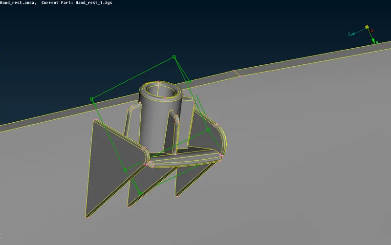
fig 6
Go to box morphing >> move option>> select the box and move accordingly.
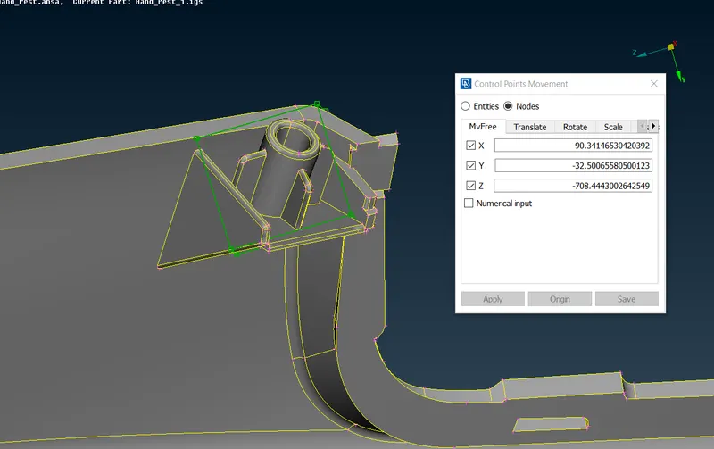
fig 7
After adjusting the geometry, middle click on the mouse to change the shape of geometry.
The final morphed shape.
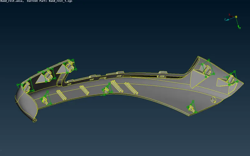
fig 8