Week - 8 - Morphing
WEEK - 8 – MORPHING
AIM:
In this challenge, There will be two models.
1) Practice all the Morphing techniques that were shown in the video for Model-1.
2) Perform morphing for the Model-2 and Increase the Height of the Dog houses and Ribs.
MORPHING
Morphing is the changing terminology or it is used to change the shape or design of the component without any numerical input.
Morphing is a process of smoothly transforming topology as well as cross-sectional properties of CAE components. It has become an integral part of the process of structural design optimization in various CAE disciplines. The morphing requirements can vary from simple transformation of design feature to very complex interaction of various design optimization parameters. ANSA provides powerful pre-processing tools along with the superior FE and geometry morphing capabilities. Unique combination of ANSA functionalities and strategies developed using insights gained by working on various client processes provide a robust platform for design optimization applications in various fields. Automation and morphing tools last mile usability has been further extended to provide easy to use and simple to understand techniques. These advanced techniques allow engineers to gain better insight for improving product design. Many of such solutions have been provided for setting up complex optimization model set-ups and are being used by major automotive OEM’s.
EXAMPLE:
1]Honda Brio (Hatchback version) and Honda AMAZE (Sedan version of Brio).
2]Toyota Etios (Sedan version of Brio) and Toyota Etios Liva(Hatchback version).
PROCEDURE:
In here we get to know about how a model will be look like when design is change.
Morphing can be done in many ways but here we are using only FREE - FREE morphing method it’s a basic step of morphing. Here we just morph the given CAD model at any direction we want so that it giving a new shape and new size.
Steps to follow in Short: Import Cad Geometry and do Geometry clean-up with no topological error-->TOPO-->Morphing
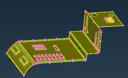
Import the given CAD model into ANSA
FILE >> OPEN >> CAD MODEL
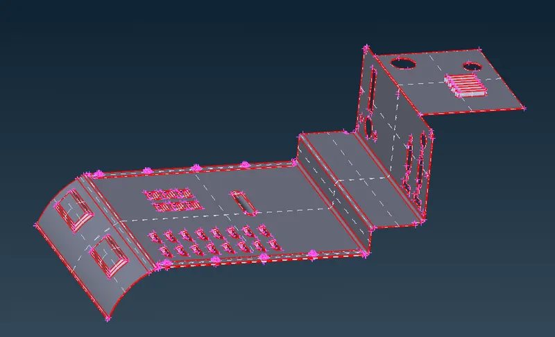
CAD Model
Now check the model for geometry check on top of commands select geometry check. this displayed some errors of triple cons
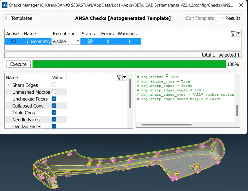
GEOMETRY CHECK
Here we need to fix those errors by using control A then right click and fix
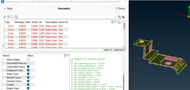
GEOMETRY CHECK
Single Cons(represented by red colour lines) - Edges which are shared with only one surface should be single cons. Single cons denote there is no connectivity between the surfaces in the model.
Double Cons(represented by yellow colour lines) -If any edge shared with two surfaces the that line is called Double Cons.
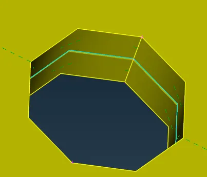
TRIPLE CONS
Triple Cons(represented by cyan colour lines) – if any edge is shared with three or more than three surfaces then that line is called triple cons.
TOPO
Topology describes how elements are bounded and connected and Geometry describes the shape of each element.
T Now the errors are fixed we can proceed for morph techniques
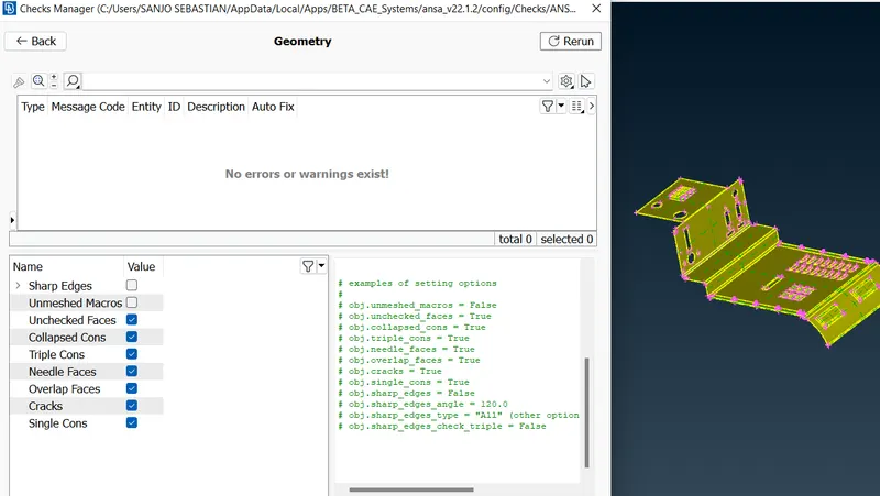
GEOMETRY CHECK
Before move to morphing mode first set the proper orientation and change the perimeter length to 1mm
MESH MODE >> PERIMETER >> LENGTH >> 1mm
First lock all bolts and nuts and hide it.
Go to morphing deck
MORPH MODE >> BOXES >> NEW >> ORTHO >> GEOMETRY(Then select faces for morphing)
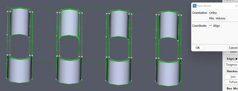
Morphing Box
Here we can create boxes under morph module buttons.
This morphing box have control grid so this box will move along the control grid only. Control grid can be moved by numerically or by our panel input this based on the global co-ordinate. If you want a local co -ordinate can also be made by right clicking in mouse by choosing Entities and a line in the morph window. Now we can increase the size of the CAD by specific measurement. Here the intial measurement of CAD is 10mm and plate thickness is 2mm. So now total height of CAD is 12mm. Now changing the size of CAD
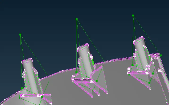
Extending
MORPH MODE >> BOX MORPHING >> MOVE >> SELECT NODES or ENTITIES >> Middle click >> Extend.
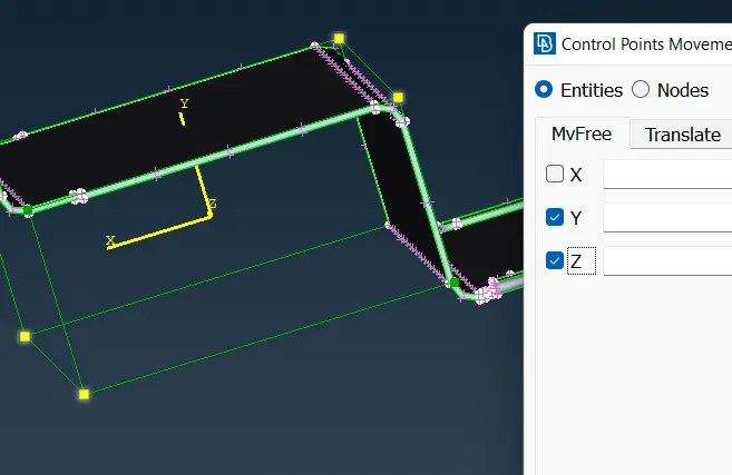
Movements of Nodes/Entities
Once the morphing is done Morphing Box can be deleted.
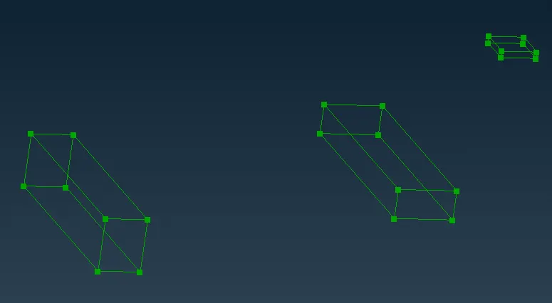
Morphing Boxes
Boxes >> Delete
Box morph can be split into number of entities. To Morph it in much a better way. This will create a number of additional boxes which may help us to do minute changes to the CAD.
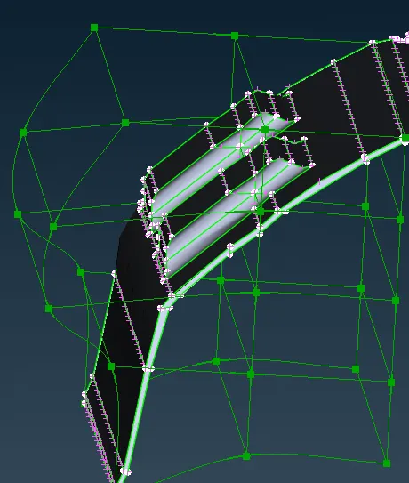
Splited Morphing Boxes
LEARNING OUT COMES:
1]Learned how to do basic of morphing techniques.
2]Learned how to create a morph box.
3]Learned how to move morph box by selecting entities or nodes.
4]Learned how to change the design of given CAD model.
5]Learned how to offset under morph mode.
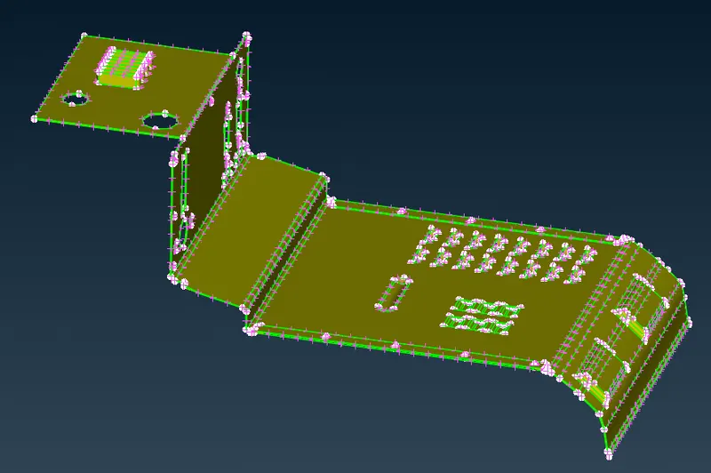
Final Image of Component After Morphing

Final Image of Hand Rest After Morphing
CONCLUSION:
Successfully performed basic morphing technique for a given CAD model and reshape or change in design has been done.