Week 8 Challenge
Q1.
To apply the loads in STAAD.Pro as per the given specifications, follow the steps below:
-
Open the STAAD.Pro project in which the structure has been modeled.
-
Go to the Loads tab and click on New Load Case. Create a new load case called "DL" for Dead Load.
-
In the Properties section, select "Self Weight" and click on Add. This will apply self-weight to the structure.
-
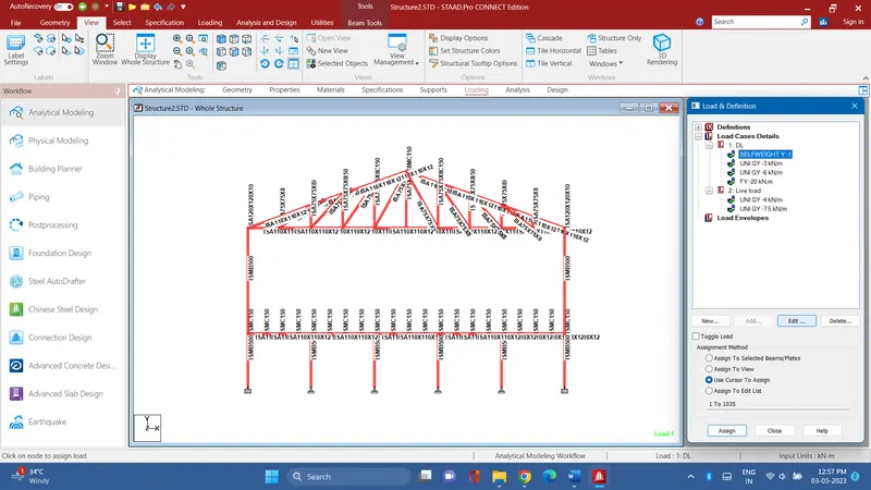
To apply a member load of 3 kN/m on the rafter, select the members of the rafter and click on the "Member Load" button in the Properties section. Enter the magnitude of 3 kN/m and the direction of the load.
-
To apply a member load of 6 kN/m on the secondary beams, select the members of the secondary beams and click on the "Member Load" button in the Properties section. Enter the magnitude of 6 kN/m and the direction of the load.
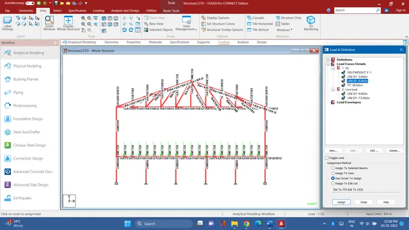
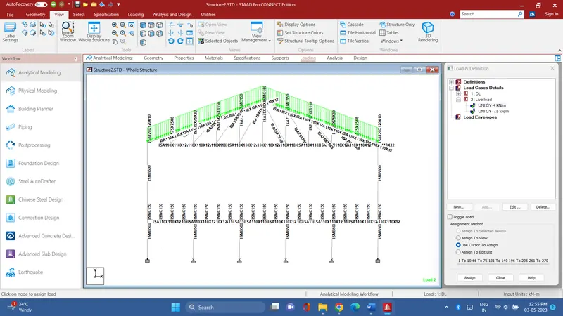
-
To apply a point load of 20 kN at the node intersecting inclined member on the top chord, select the node and click on the "Point Load" button in the Properties section. Enter the magnitude of 20 kN and the direction of the load.
-
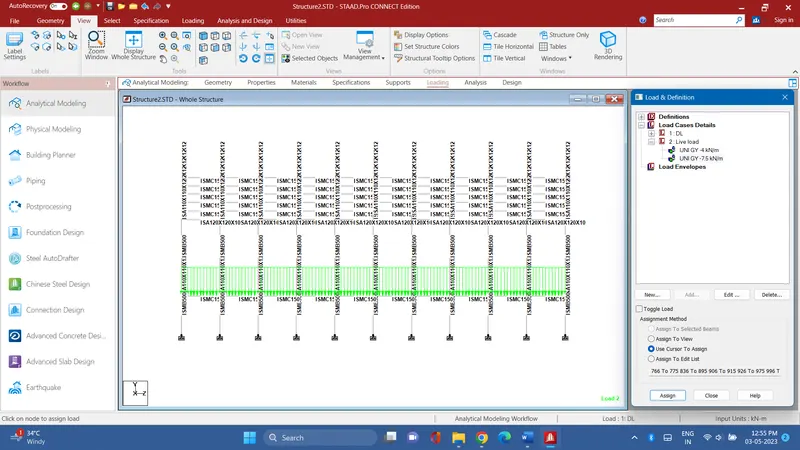 Repeat steps 2-6 to form a Load Case called "LL" for Live Load and apply member loads of 4 kN/m on the rafter and 7.5 kN/m on the secondary beams.
 -
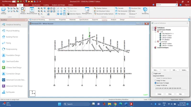 To form a load combination of 1.5DL+1.5LL, go to the Load Combination tab and click on New Load Combination. Enter the name of the combination as "1.5DL+1.5LL" and select the load cases "DL" and "LL". Enter the factors of 1.5 for both load cases and click on Add.
 -
Save the project and analyze the structure to ensure that it meets the design requirements under the applied loads.
Q2.
To find the maximum force and minimum force for each member in the STAAD.Pro model, follow the steps below:
-
Open the STAAD.Pro project in which the structure has been modeled and analyzed.
-
Go to the Post Processing tab and select the member for which you want to find the maximum and minimum force.
-
Click on the "Member Force Envelope" button in the Analysis Results section.
-
In the Member Force Envelope dialog box, select the load combination "1.5DL+1.5LL" and click on OK.
-
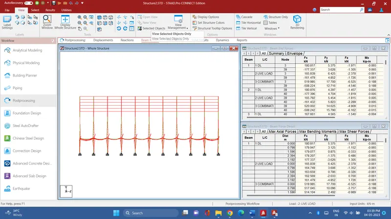
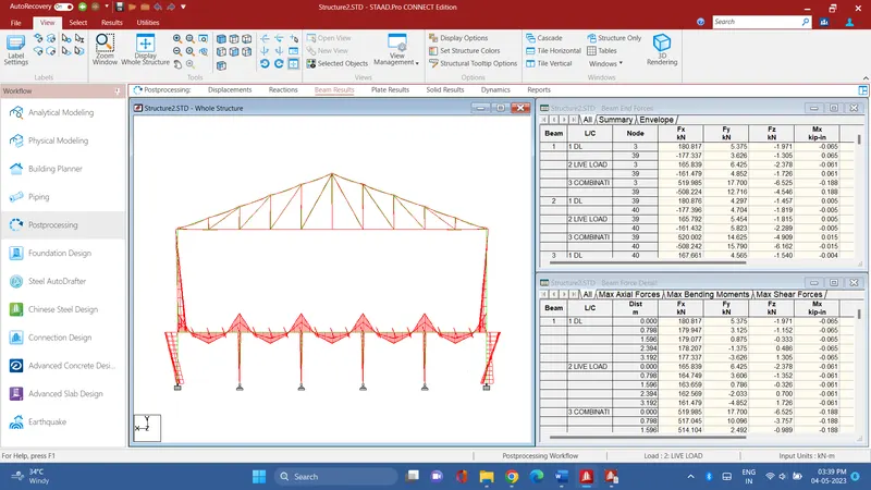
The maximum and minimum forces for the selected member will be displayed in the Member Force Envelope graph.
-
Repeat steps 2-5 for each member in the model to find the maximum and minimum forces.