Week 8 - Challenge 6 - Core & Cavity Design
SWITCH BEZEL
AIM:
The aim of the project is to create a switch bezel plastic component using the given class A surface following the OEM standard. and perform the draft analysis.
CLASS-A SURFACE:
The class-A surface is used in the automotive design industry. it describes the final production surface data for the aesthetic parts.
TOOLING DIRECTION:
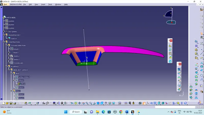
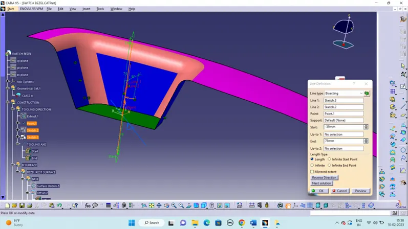
Considering the Ejection from the cavity of the mould after manufacturing the interior trim (switch bezel) must have the nominal 3-degree draft angle. Hence the tooling direction is created by considering the above factor and bisecting method is used. The base surface of the class – A was extracted and a point at the centre is created and an axis system was inserted to the point with the current feature is disabled. Then, using project intersection along yz plane is created and the two inclined lines were drawn inside the positioned sketch. Then bisecting lines with the two inclined lines were drawn. The same procedure is done along the xz plane but on one side we don’t have inclined lines so the centre point is used to extrude a line along the z-direction and gave a measurement of 6 degrees (Tentatively). With these two lines from sketches 1 and 2, the bisecting line is crated and published as Tooling Axis(MAIN TOOLING DIRECTION).
CLASS-B SURFACE:
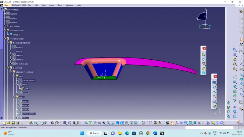
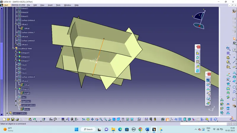
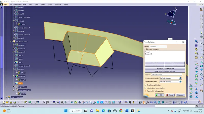
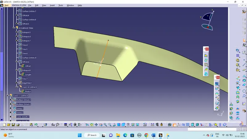
For creating the class-B surface the required surface except the offset surface have been extracted and then untrimmed all the surface. Then all the surfaces have been extrapolated to get intersections between them. The thickness of the Switch bezel is 2.5mm the B-Surface was offset to 2.5 mm and the required trim operations must be carried out. Finally, the required corners have been filleted.
FILLET VALUE = THICKNESS - GIVEN FILLET VALUE
FILLET VALUE 1 = 15 – 2.5 = 12.5
FILLET VALUE 2 = 14 – 2.5 = 11.5
CLASS-C SURFACE
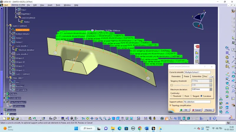
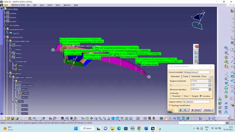
The required outer edges of the A-Surface were extracted using Multiple Extract. Then for avoiding the patches the curve is smoothened using the Curve Smooth option. Then by using the sweep command the surface was created. For creating the smooth surface I execute the smooth curve option and then I replace the extract 1 and 2 to curve smooth definition 1 and 2.

FINAL OBJECT:
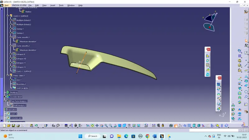
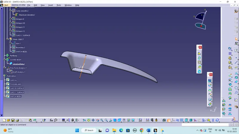
Now the class – A and Class- C surfaces were joined together by removing the gaps in-between them with the help of extrapolation (tangent continuity) and Trim surface from joined surfaces and class-B surface. Then the exact surface of the Switch bezel. Finally by defining the part body by using the Closed Surface command in Part Design, the component's solid body is created.
CLOSED BODY:
DRAFT ANALYSIS:
The draft analysis command enables you to detect if the part you drafted will be easily removed. This type of analysis is performed based on colour ranges identifying zones on the analysed element where the deviation from the draft direction at any point, corresponds to specified values.
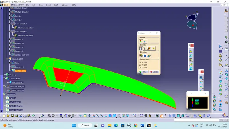
FOR CLASS A SURFACE:
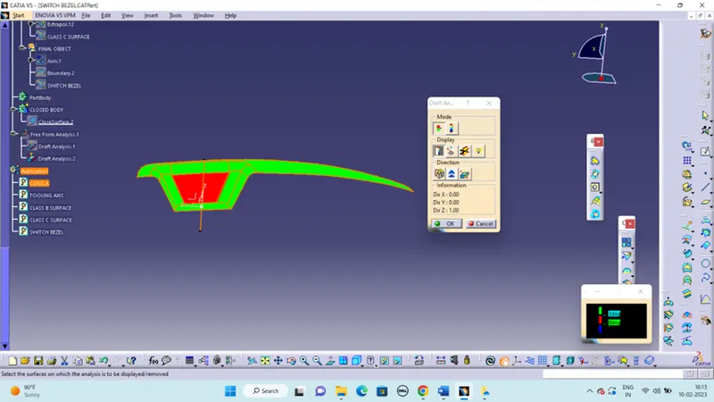
PUBLICATION:
by selecting the tooling axis, class A class B and class C surface and final object publish it by going to menu bar> tools> publication. this will be published under the publication tab in a tree structure.
MULTIPLE VIEWS AND TREE STRUCTURE:
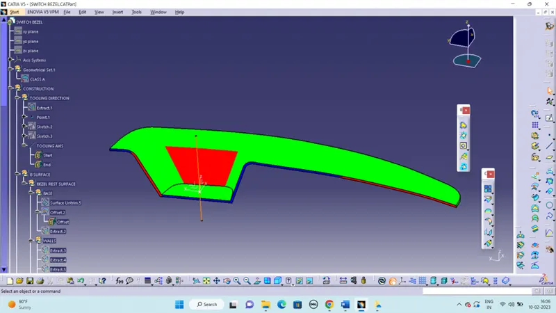
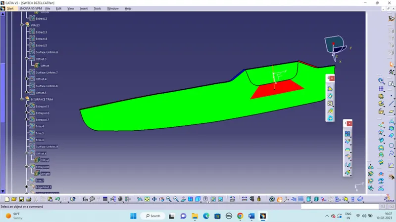
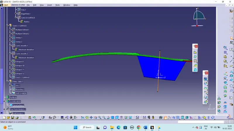
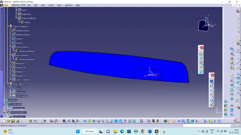
ISOMETRIC VIEW:
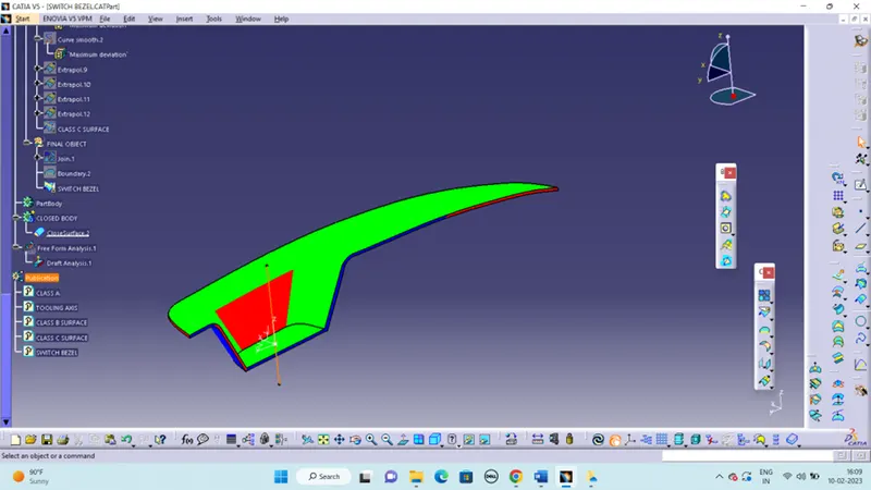
CORE AND CAVITY:
The Mould Core & Cavity are the shaped sections in either half of the mould tool which give the plastic product its final shape. The hot molten material is injected into the core & cavity and then sets hard into shape. The design of the core & cavity is essential in the correct formation of the product.
Essential elements of the Core & Cavity :
Gate:
This is the point between the runner and the core & cavity. Often it is designed to be slightly narrower than the runner, so that the plastic there is thinner when it sets, forming a natural weak point for easier removal of the runners. The tool needs to be designed carefully so that gates are in the right place to ensure correct filling of the core & cavity. As the placement of gates always remains visible on the moulded part, the tool also needs to be designed in such a way that the gates don't detract from the aesthetics of the finished product.
Runner:
Runners allow the passage of the molten plastic materials to the core & cavity. Runners can also be hot or cold. Hot runners are more expensive but provide much greater flexibility for the positioning of gates (because they allow a gate to be much smaller) and they also reduce wastage because the plastic inside the runner stays hot and is used for the next part." alt="Mould core.
CORE :
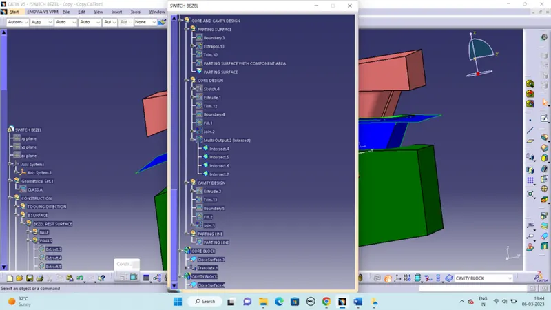
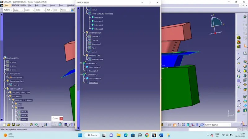
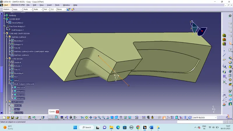
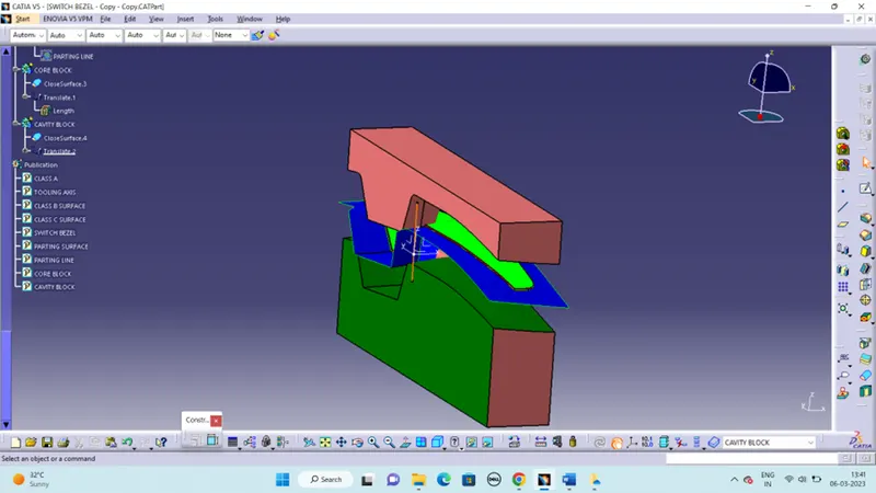
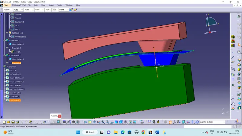
The core design is started with extracting the parting surface that becomes the datum for the core and cavity. The parting surface in most of the cases is kept at the B class surface to avoid close and tight contact between the core and cavity. the A-class surface is extrapolated with some length and later it is trimmed with a C surface. Then A and C surface again trimmed with B surface to form the core face. The final core block is made by drawing the boundary sketch and extruding it along the tooling axis direction followed by the filling and thickening.
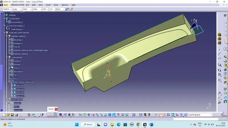
CAVITY:
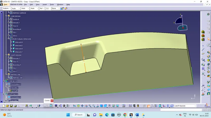
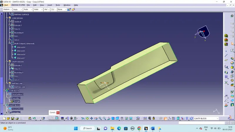
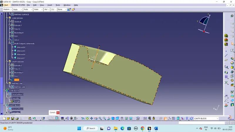
The cavity is the part where the injector and filling of the molten plastic happens. The cavity block is prepared by first extruding the outer boundary along the tooling direction. This outer surface is trimmed with the B surface and then it is filled and thickened.
PARTING LINE:
The parting line indicates the direction of the line of draw for the mold, or the point where you can separate the two halves of the mold to release the part without damage. Usually, the parting line is down the middle of the part, but this varies due to part geometry.
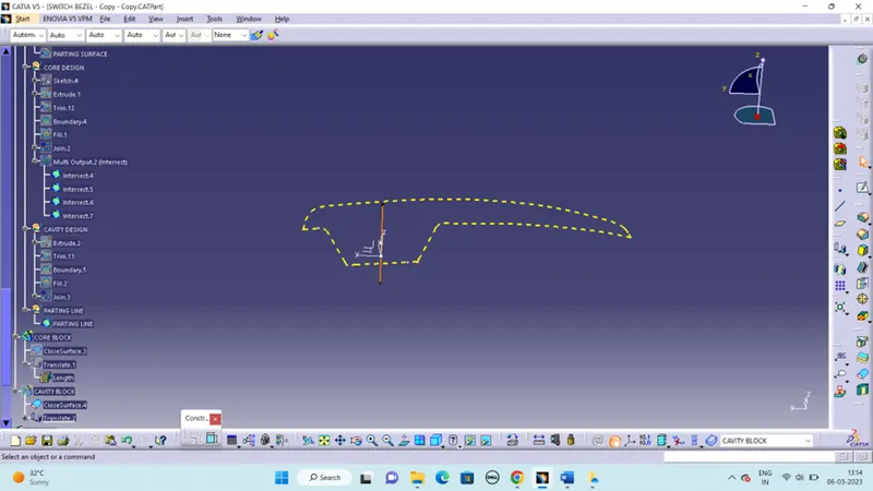
PARTING SURFACE:
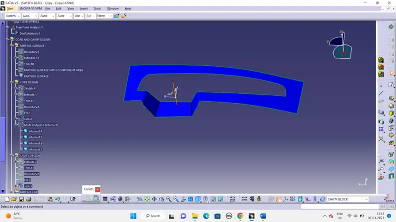
The parting surface of a mould are those surfaces of both mould plates adjacent to the impressions which butt together to form a seal and prevent the loss of plastic material from the impression. The parting surfaces of a mould are those portion of the mould plates, adjacent to the impressions, which butt together to form a seal and prevent the loss of plastic material from the impression.
PARTING SURFACE WITH COMPONENT AREA:
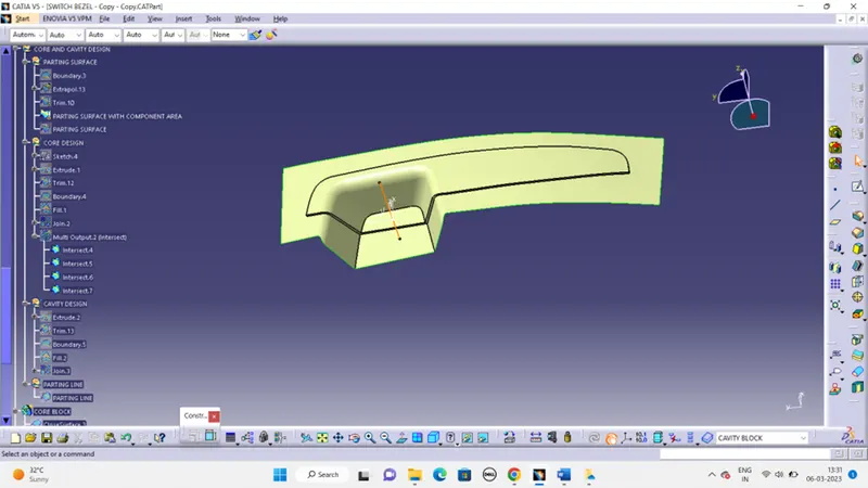
PARTING SURFACE:
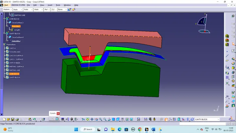
TREE STRUCTURE FOR CORE AND CAVITY DESIGN: