Week 8 - Challenge 6 - Core & Cavity Design
WEEK-8,CHALLENGE-6
CORE & CAVITY DESIGN -MAYANK TIWARI
OBJECTIVE - TO CREATE CORE & CAVITY BLOCKS FOR THE SWITCH BEZEL COMPONENT.
DESCRIPTION :
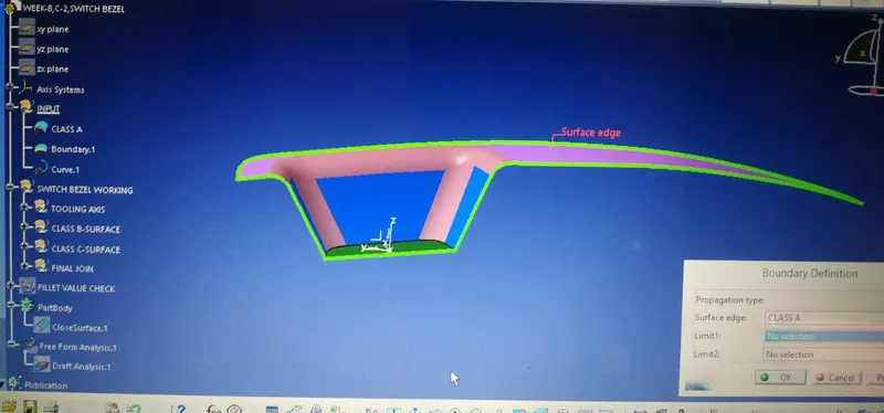
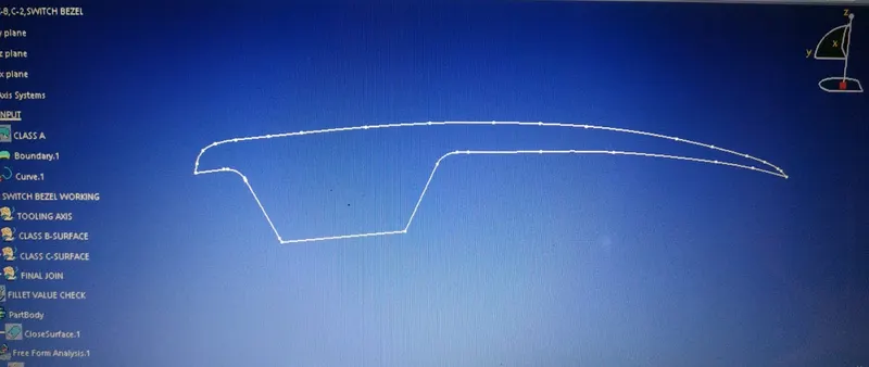
1. CONTINUITY CHECK OF THE GIVEN CLASS-A.
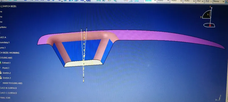
2. TOOLING AXIS CREATION.
The Tooling Direction is basically the direction that the mold pulls a part. The mold is built in two separate pieces, basically. You have a Cavity side and you have the Core side. The Core pulls apart from the Cavity and that's the Dye line or the Tooling Direction.
- Considering the Ejection from the cavity of the mould after manufacturing the interior trim (switch bezel) must have the nominal 3-degree draft angle.
- Hence the tooling direction is created by considering the above factor and bisecting method is used.
- The base surface of the class – A was extracted and a point at the centre is created and an axis system was inserted to the point with the current feature is disabled.
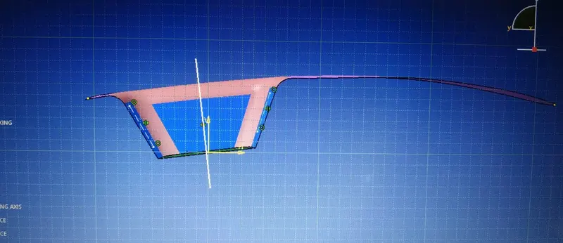
- Then, using project intersection along yz plane is created and the two inclined lines were drawn inside the positioned sketch.
- Then bisecting lines with the two inclined lines were drawn.
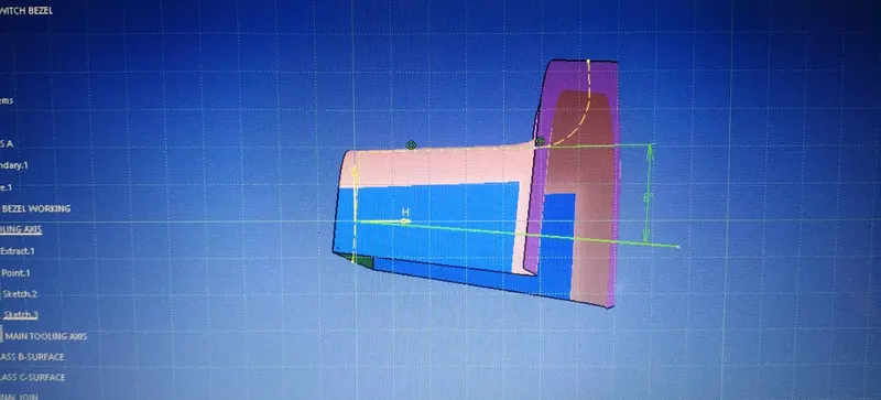
- Now the same procedure is done along the xz plane but on one side we don’t have inclined lines so the centre point is used to extrude a line along the z-direction and gave a measurement of 5 degrees (Tentatively).
- With these two lines from sketches 1 and 2, the bisecting line is crated and published as Tooling Axis(tooling direction).
3. DRAFT ANALYSIS 0N CLASS-A & FINAL SOLID BODY.
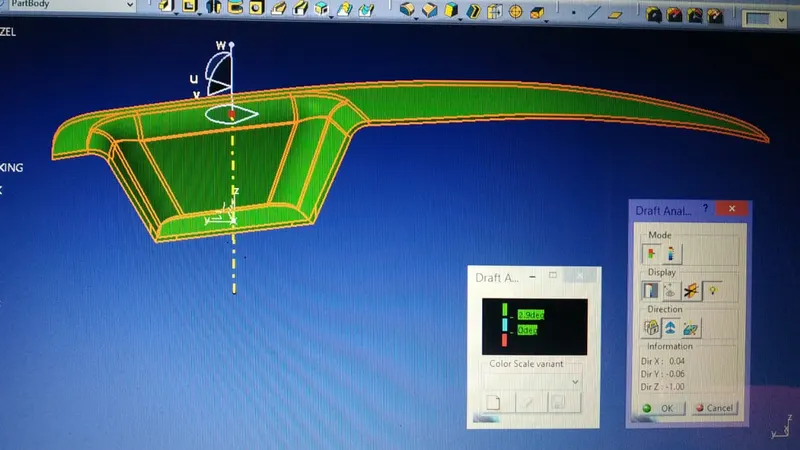
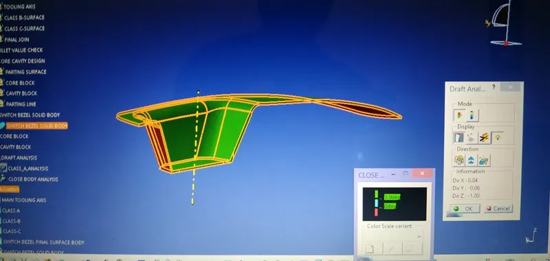
The Draft Analysis command enables you to detect if the part you drafted will be easily removed. This type of analysis is performed based on color ranges identifying zones on the analyzed element where the deviation from the draft direction at any point, corresponds to specified values.
- Before going to drat analysis go to customized view parameter >under mesh >check material and then click ok.
- Now for draft analyses go to insert » analysis » feature draft analysis.
- Use the compasss to define the draft direction.
- In the colour scale change the draft angle to 3 degree.
- The component changes to green in indication of passing draft angle.
- Use running point to check the angle on the component.
CLASS-A
SOLID BODY
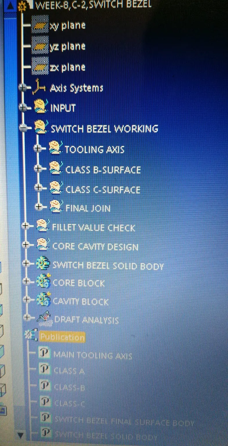
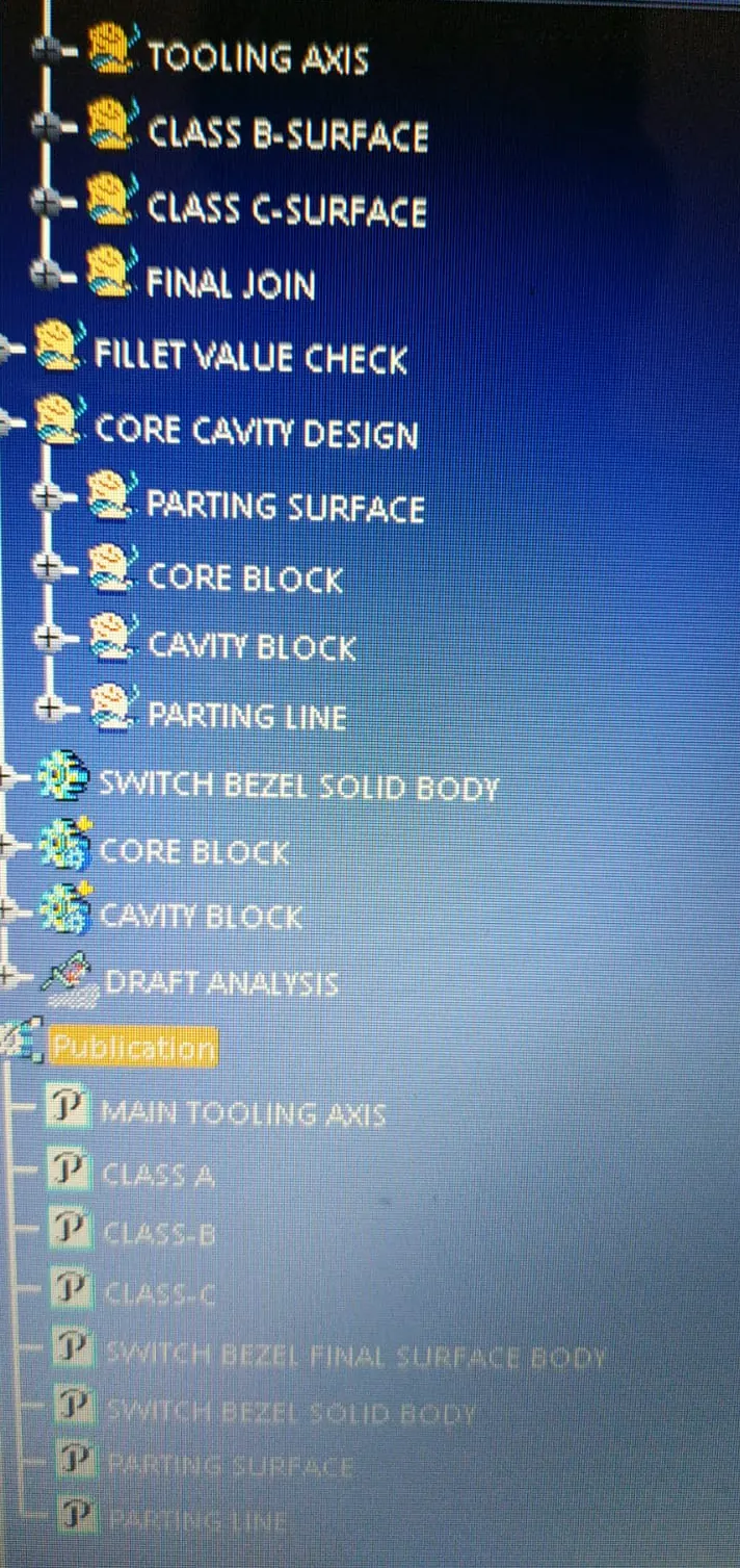
4. TREE STRUCTURE & PUBLICATIONS.
 .
. 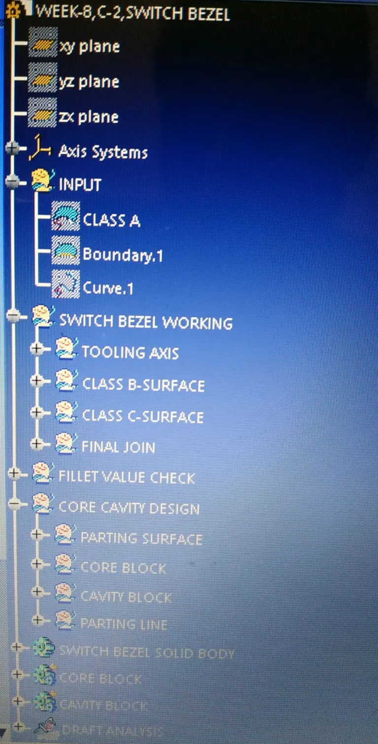 .
. 
5. SWITCH BEZEL SURFACE & SOLID BODY.
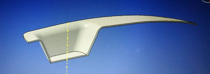
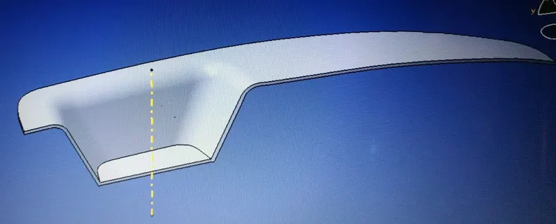
6. PARTING LINE & PARTING SURFACE.
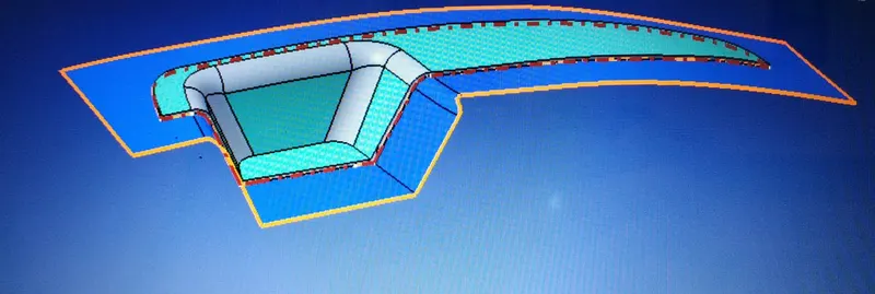
HERE BLUE SURFACE IS THE PARTING SURFACE & BROWN DOTTED LINE IS THE PARTING LINE.
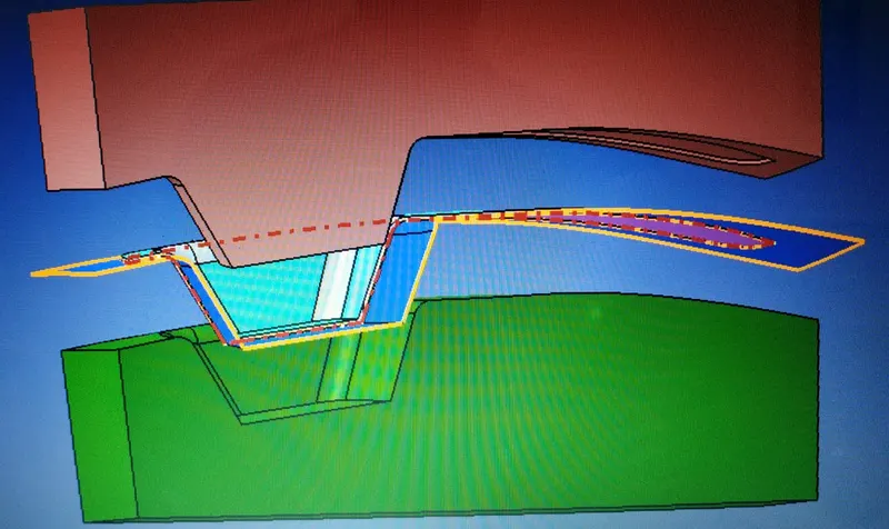
7.CORE & CAVITY BLOCK.
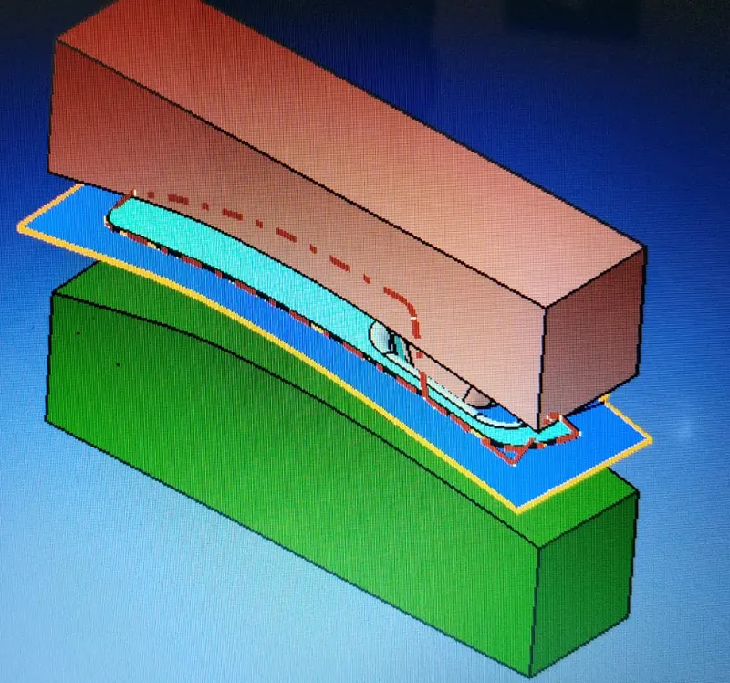
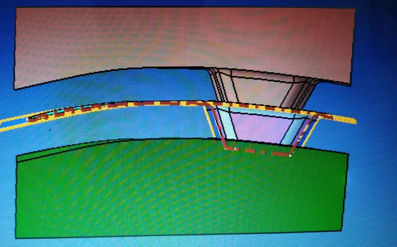
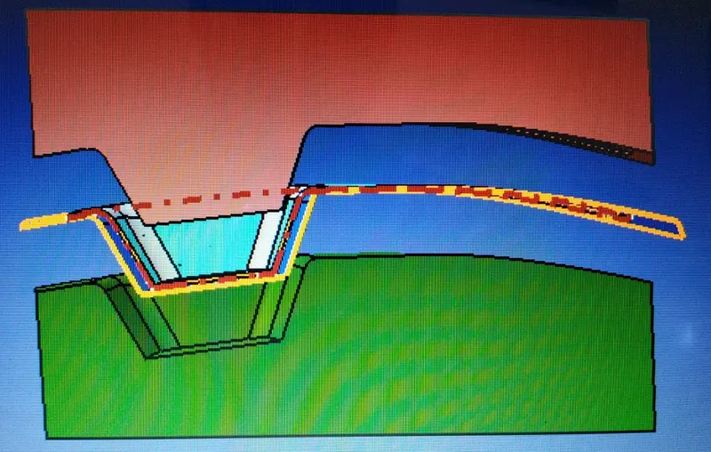
# CATPART FILE IS ATTACTHED BELOW.