Week 8 - Challenge 6 - Core & Cavity Design
Challenge 6 - Core & Cavity Design
AIM :
To create the Core and cavity blocks for the Switch Bezel Component.
OBJECTIVE :
- To Create Core, Cavity and Parting surface for the given component along the Tooling Axis.
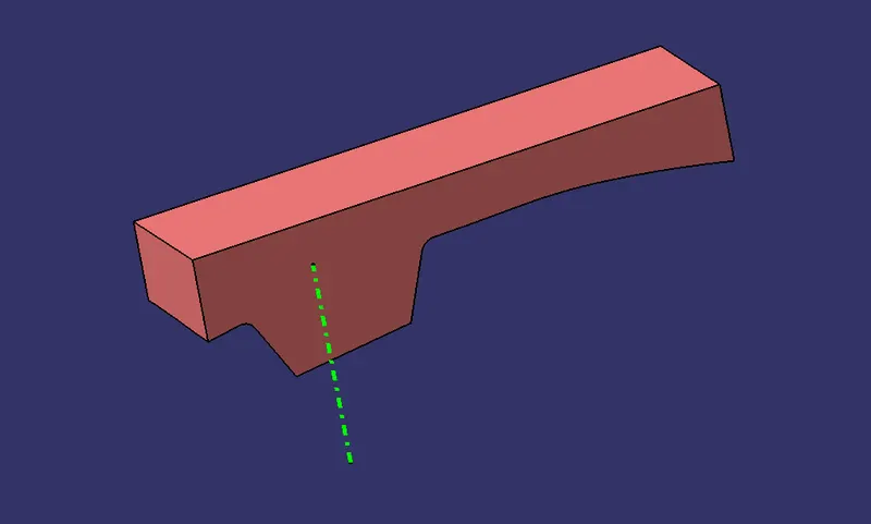
CORE :
- Core is a preformed, bonded, sand insert placed into the mold to shape the interior of a casting or a part of the casting that cannot be shaped by the pattern.
- Core is the male part which forms the internal shape of molding.
- Cores are often used to create hollow sections or cavities in a casting.
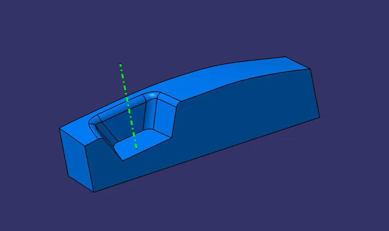
CAVITY :
- Cavity is the combined open area of the molding material and core, where the metal is poured to produce the casting.
- The cavity is the female part which forms external shape of molding.
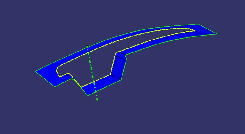
PARTING SURFACE & PARTING LINE :
- A Parting surface is a surface in the model that you designate to split a workpiece, die block, or another volume.
- A Parting line is the line of separation on the plastic part where the two halves of the plastic injection mold meet.
PROCEDURE :
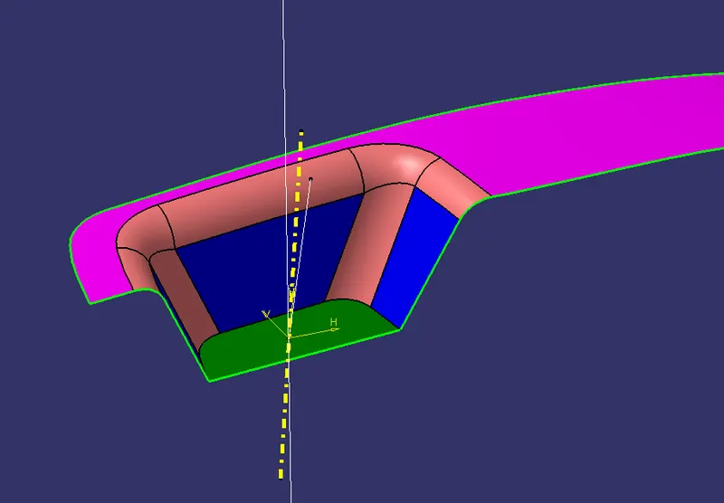
Creating Tooling Axis
- Initially the given Class-A surface was imported and checked for any discrepencies in the boundary.
- The base surface of the component was extracted.
- Two sketches were created based on the adjacent sides of the Class A surface.
- Finally a Tooling axis was created from these two reference lines using Bisecting option.
Creating Parting surface & Parting line
- Initially the Class A surface was Extrapolated.
- It was then Trimmed with the Class C surface.
- This output was further trimmed with Class B surface along with the component.
- The Parting line was created as an Intersect with Class B with a Trimmed surface.
- The Parting surface was obtained by Splitting the Parting surface with component with the Parting line.
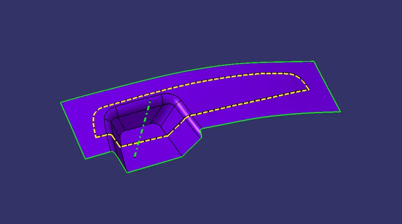
Creating Core
- A Rectangular shape was formed and extruded along the tooling axis such that it stays inside the region of the Parting surface.
- This extrude was Trimmed with the Parting surface with component to form the Core part.
- The Core was closed at the top using Fill command and was further joined using Join command.
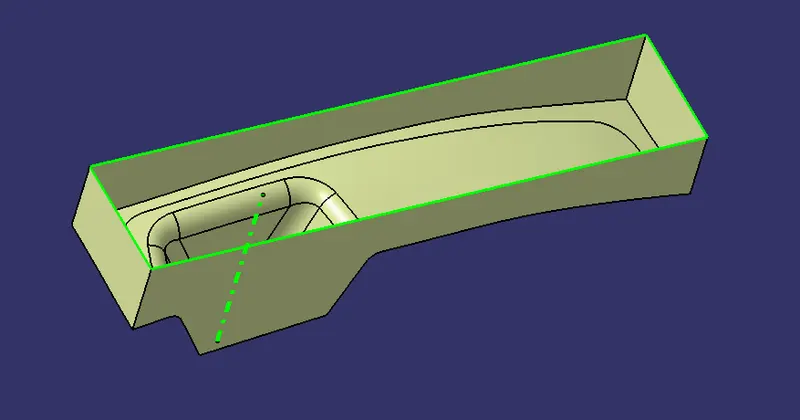
Creating Cavity
- The Rectangular extrude was usde to create the cavity aswell.
- This extrude was Trimmed with the Class B to form the Cavity part.
- The Cavity was closed at the top using Fill command and was further joined using Join command.
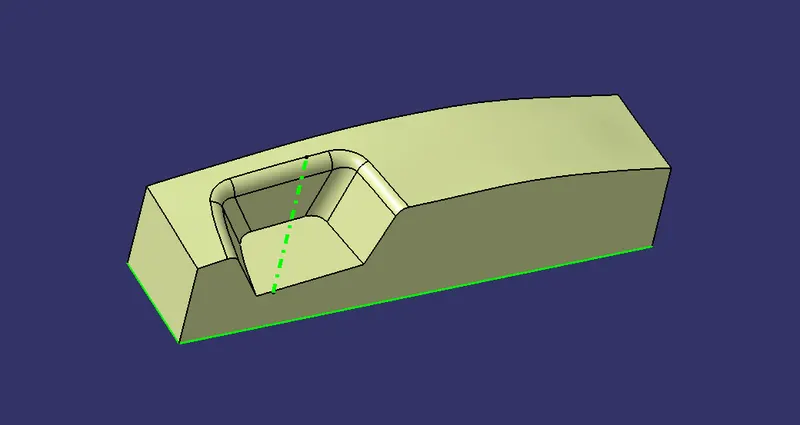
Creating Solid Body
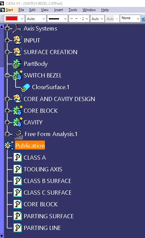
- The Core and Cavity were made into a solid component using the Close surface feature.
- The Tooling axis, Core, Cavity, Parting surface and Parting line were published.
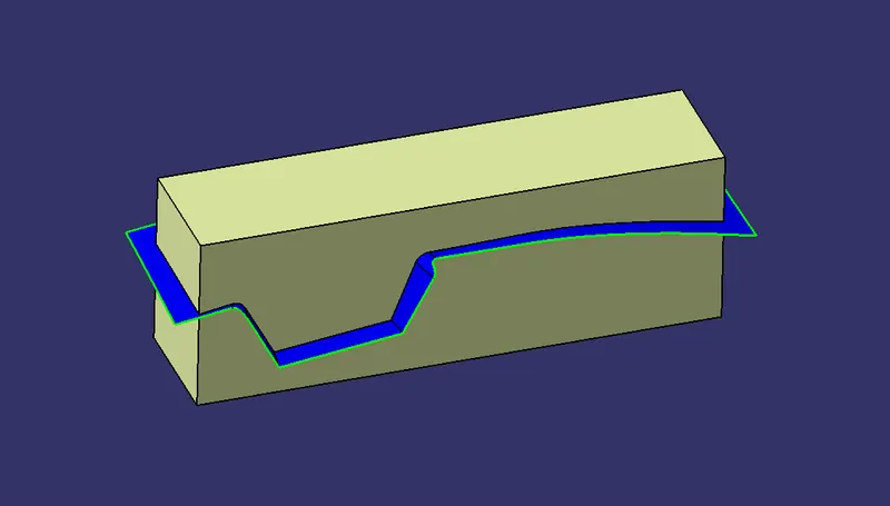
Draft Analysis
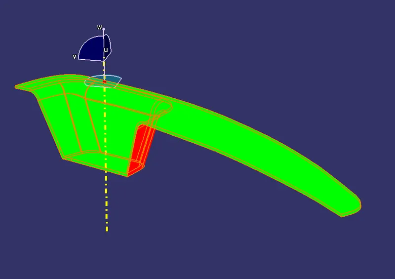
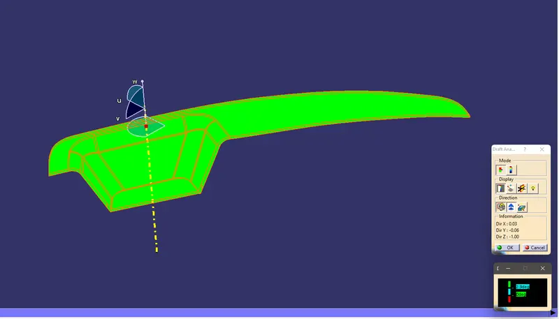
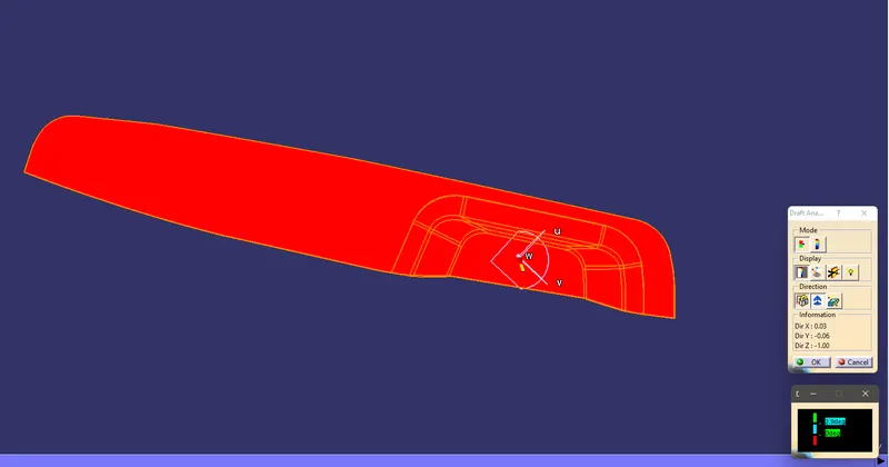
- The Drafting analysis was performed using the Feature Draft Analysis command.
- Using this command the compass was set on the main tooling axis and the Draft angle was changed to 2.9 degree.
MODEL RESULTS :
Feature tree
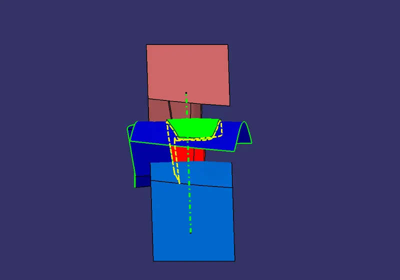
Front view
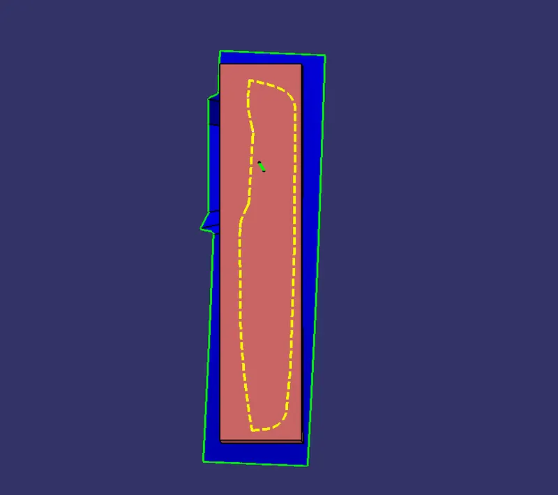
Top view
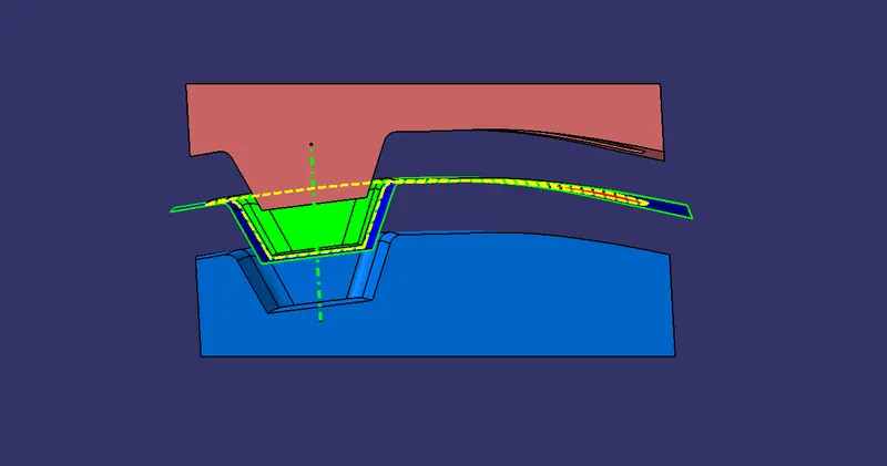
Side view
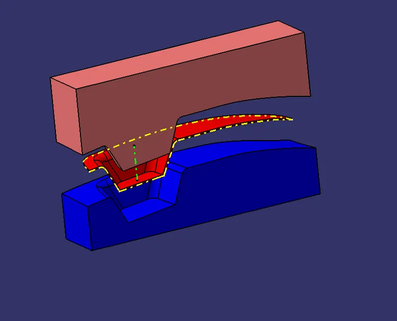
Isometric view
CONCLUSION :
- The creation of Core, Cavity, Parting line and Parting surface were done.
- The Drafting analysis was performed.
- The solid component was created from the surface geometry.
- The Translation of Core and Cavity block was done inorder to observe their operation along Tooling axis,
- The necessary screenshots and files were attached.