Week 8 - Challenge 6 - Core & Cavity Design
AIM
To create the core and cavity for the switch bezel condering the all design.
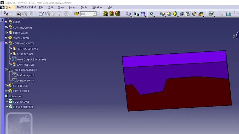
TOOLING AXIS
It is the axis in which the direction core and cavity open. This is the very important for production of plastic component .Most of the defect will done improper tooling axis creation by the plasti designer.
There are so many methods for creation of tooling axis intersect is the one of the method for creating the tooling axis.
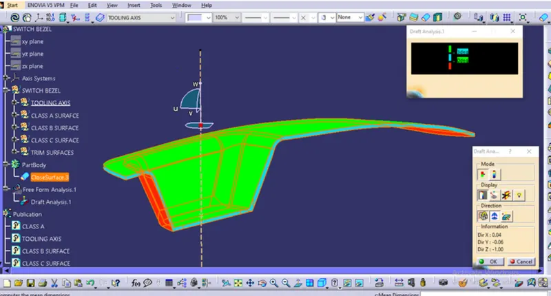
DRAFT ANALYSIS
- The purose of draft analysis is to detect the partsh add be eaisily with srawl from the core and cavity by usin of diffrection colour ranges
- This analysis will be done by draft analysis command.For this command go to insert draft analysis.
- These are the fallowing steps to do the draft analysis on switch dezel.First to click the draft analysis command the following window will be appered.
Then click the compass and on the tooling axis and then click on the part then the colour will change of the part and you can change the value using scale option and also a running pint command used to findout thengle of draft from the tooling axis .So you can modify the tooling axis by using compass to get proper result.
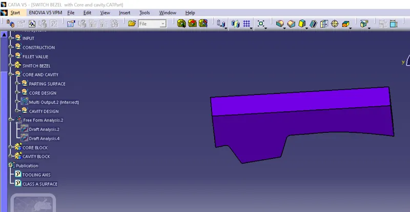
CORE AND CAVITY
A core is the one part of the mould and it is respponsible for half of the molded part .Actvally core is the projection of the body and cavity combines to from mould .Then the plastic injection into these mould to get a plastic part.
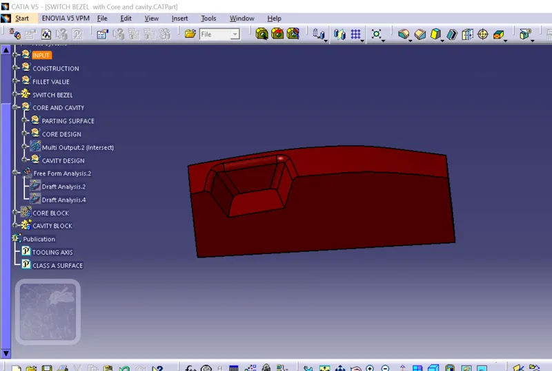
PARTING SURFACE
Injection mold has two major components one is core and another is cavity during the injection molding process these two halves are pressed tightly from a sealed hollow to avoid the melt flow leakage and maintain certain holding pressure the pressed surface are called parting surface usually parting surface are the biggest projection out line of the part.
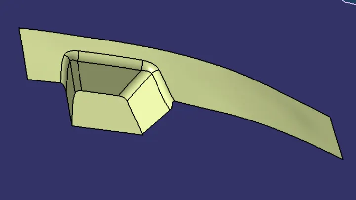
PARTING LINE
It is the area in which parting surface and component meets or it is a junction between care and cavity and the parting surface has some set of rules because the parduct quality mostly depends on the parting surface.
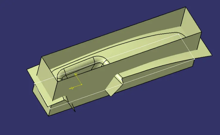
DESIGN PARTING SURFACE SHOULD FOLLOW PRINCIOLES
Design the injection mold simple as passible .Avoid or reduce side parting as much as possible to reduce complexity of the mold making.
Ease of de-molding as far as possible for instance the plastic part should stay in fixed halve on injection mold and should ejection by ejection system avoid side de-molding action.
Ensure the dimension accuraiy of the molded psrt try to make the part simiar dimension accuray requirement in same mold to reduce manufacting amd assembly errors.
Ensure apperance requirement of molded part finish or mismatch usually occurs on parting sarface So the parting surface should not be designed on high quality requirement surface.
Ensure adequate venting.If possible parting surface should be place at the end of the mold flow.This is going to be advantage of filling and venting.