Week 8 - Challenge 6 - Core & Cavity Design
The operation to do:
- Create Core.
- Create Cavity.
- Create Parting Line.
- Create Parting Surface.
- Create Draft Analysis.
Method used to manufacture:
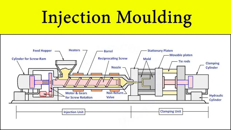
- Normaly Plastic mold is made with the help of Injection Molding. The injection molding is normally having two halves one is core and another one is cavity.both intersect to form a mold.
Tooling Axis:
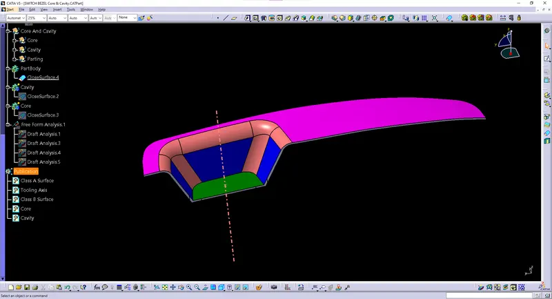
- The tooling axis for this component will be created from the Y component. This should be done using the method of extracting the plane surface and Creating a point in the plane using a point on the surface. And finally, the line should create using the normal surface.
Core:
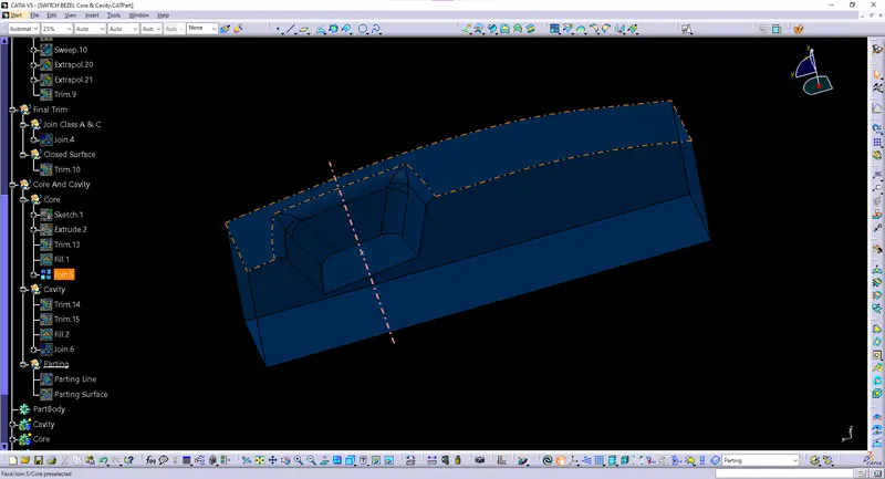
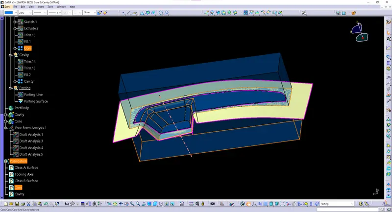
- Core is a movable part, having the ejection pins, which is used to eject the mold from the core. A core is a preformed, bonded, sand insert placed into the mold to shape the interior of a casting or a part of the casting that cannot be shaped by the pattern. Cores are frequently used to create hollow sections or cavities in a casting.
Cavity:
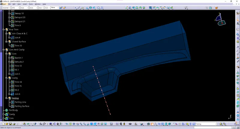
- Cavity is fixed part, which is not available. A mold is a hollow form typically made from stainless steel that has plastic injected into it to manufacture a plastic part. The plastic is inserted into the mold cavity, which is a hole in the mold shaped like the desired part.
Parting Line:
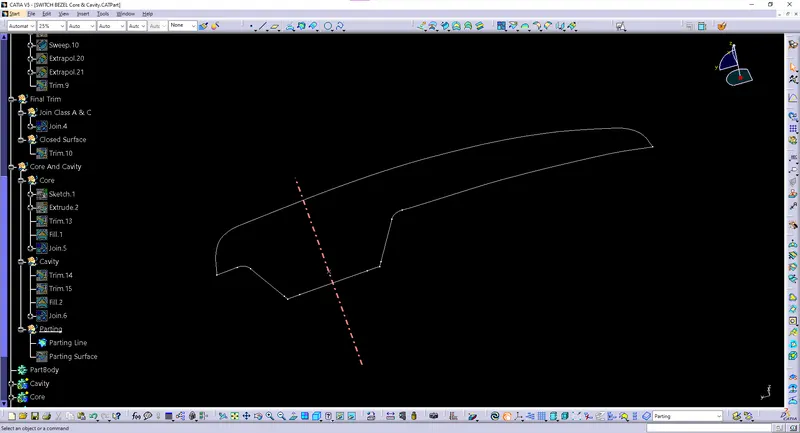
- Parting line is a line lies between Core and Cavity. But in the concept of Molding it lies between the surface of A & C Surface or B & C Surface. The line or plane along which sections of a foundry mold, die, or pattern separate.
Parting Surface:
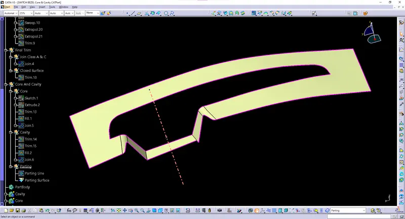
- The surface which meets the core and cavity is known as parting surface A parting surface is a surface that separates the mold block into two parts – the core and the cavity. Consider a model, as shown in the image above. As you can see, the model is a hollow plastic component. To make a mold for this part, you should first select a parting line for the mold.
CLOSED SURFACE:
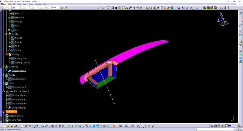
Closed Surface is formed from part body.
Overall Surface
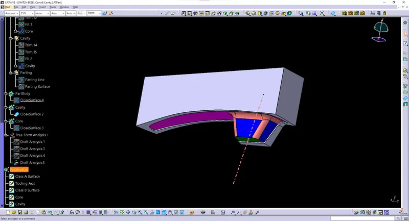
Cavity
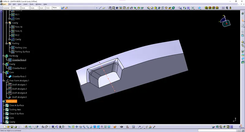
Core
Other Drawing:
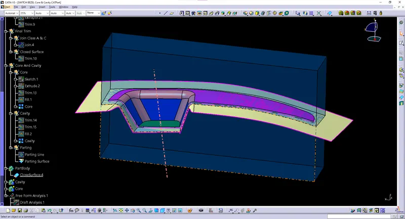
Draft Analysis:
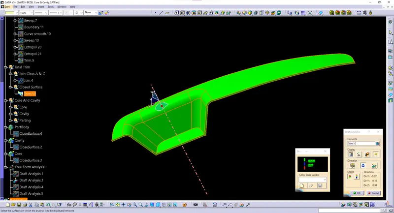
- The draft analysis technique is used to analyze whether our part model created in CAD is manufacturable based on the draft condition applied. Here the part should get easily removed from the panel dies (in case of Sheet metal part) or Mold (in case of plastic). The analysis shows whether the angle given on the surface is up to the level or not. This can be identified by using Green, Blue, and Colour. Green means to perfect (< 2.9deg), Blue (0deg), and Red (> 2.9deg).
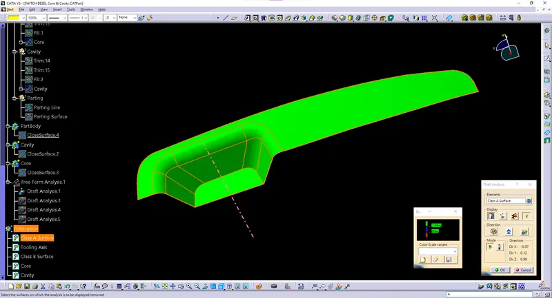
DRAFT ANALYSIS OF CLASS A SURFACE
DRAFT ANALYSIS OF OVERALL SURFACE
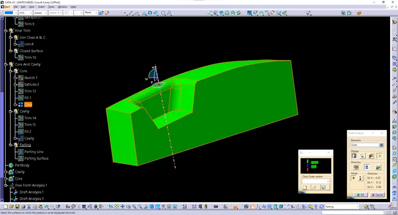
DRAFT ANALYSIS OF CORE
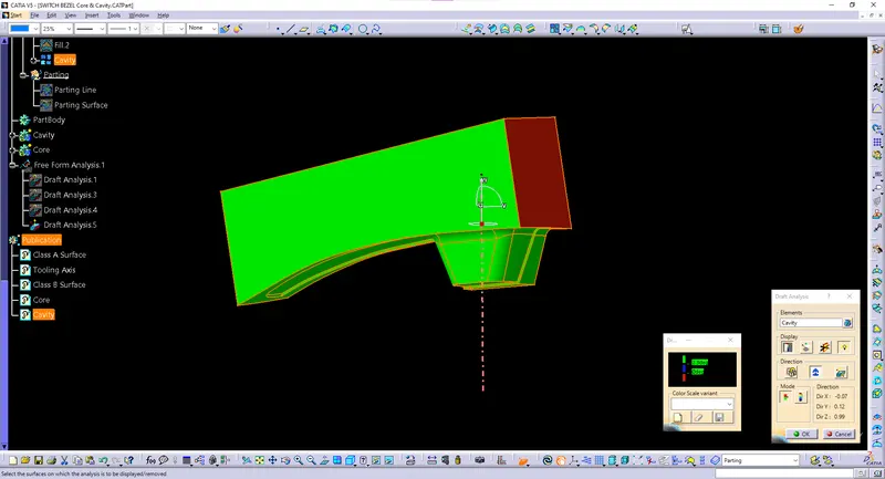
DRAFT ANALYSIS OF CAVITY
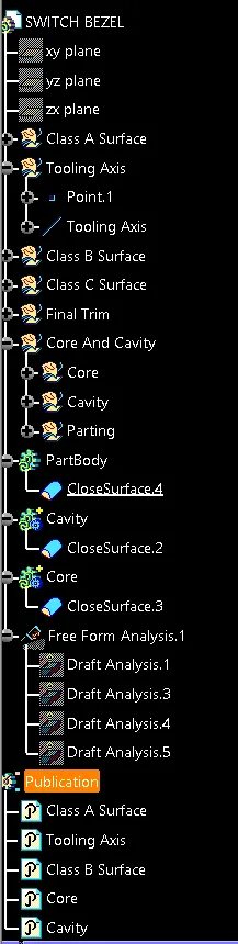
FAMILY TREE