Week 8 - Challenge 6 - Core & Cavity Design
CORE AND CAVITY DESIGN
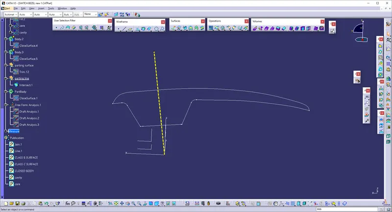
TOOLING AXIS : Tooling axis means the direction in which core and cavity open and close.Tool is nothing burt mold, tooling axis is created to know in which direction the mold open and close, parts drafts are given along this axis.
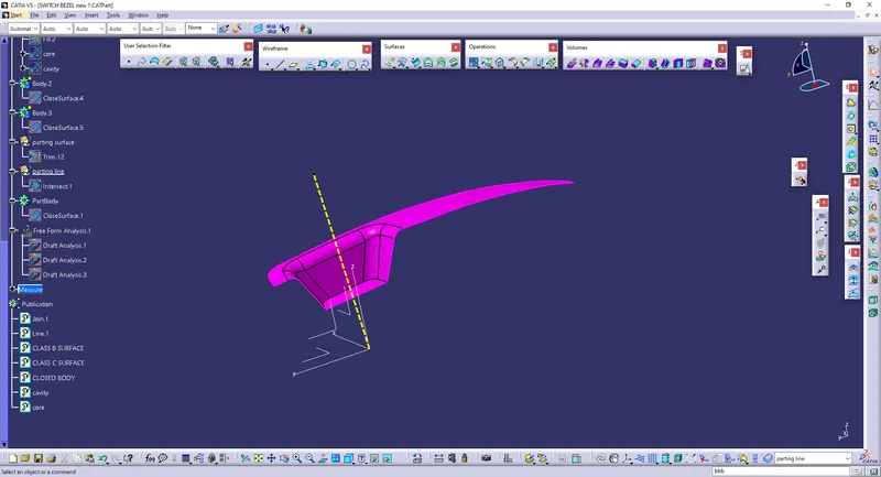
PLASTIC COMPONENT DRAFT ANALYSIS
DRAFT ANALYSIS 1
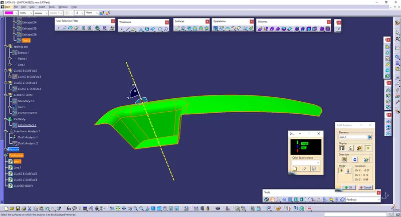
DRAFT ANALYSIS 2
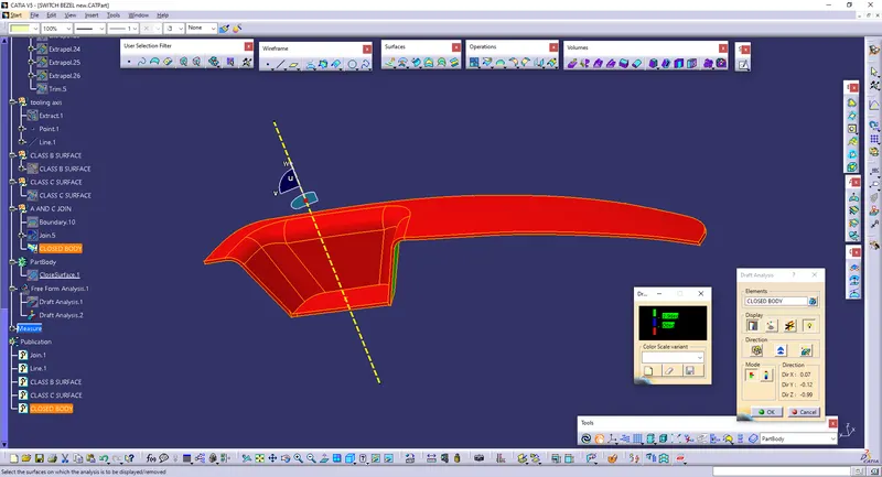
Core & Cavity design:
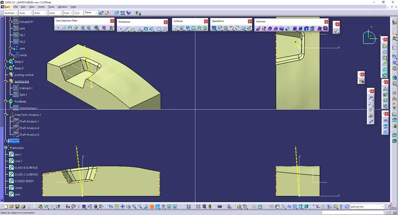
Core: It is one half of the tool which is movable along the tooling axis in a mold. And it has the projection with some drafts required to manufacture the plastic components.
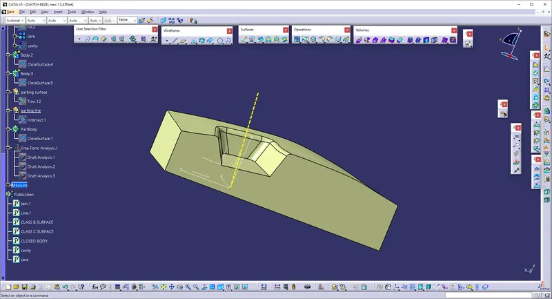
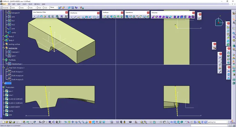
Cavity: It is another half of the tool which is stationary at the base of a mold with some cavity for injecting the molten plastic into it to form the required part. It has some ejector pins in it which is used to eject the molded part out of the mold.
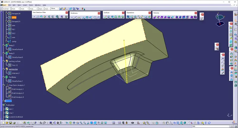
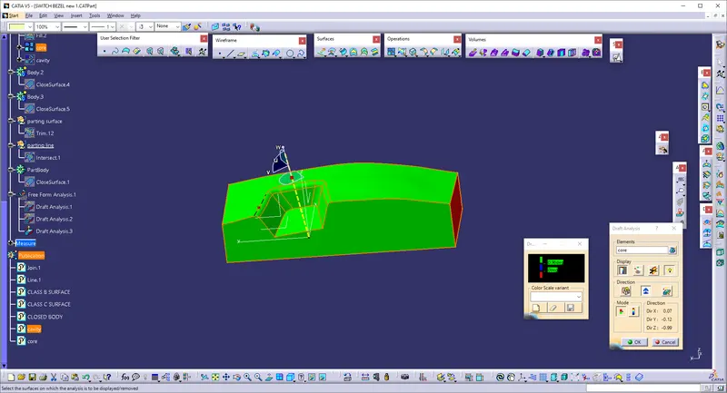
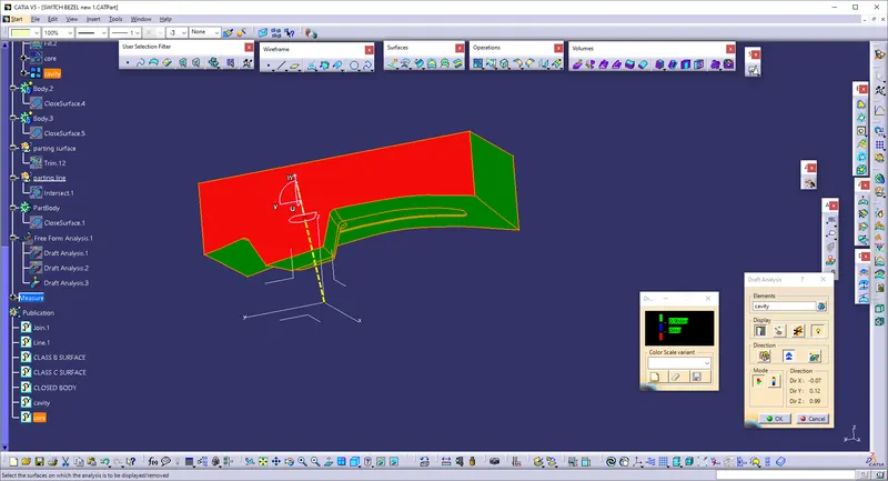
DRAFT ANALYSIS : Draft analysis is done to check weather the tooling axis and draft angle are correct or not and to find weather the component is manufactured and ejected or not. Draft Analysis is a tool in CATIA which identifies the zones which deviates from the specified values of angles along a defined draft direction using colour codes.
DRAFT ANALYSIS CORE 1
DRAFT ANALYSIS CAVITY 2
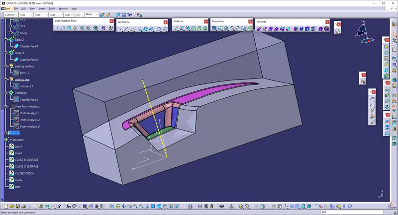
Parting surface: This is the surface were the core and cavity meets, after the clamping process for injection.
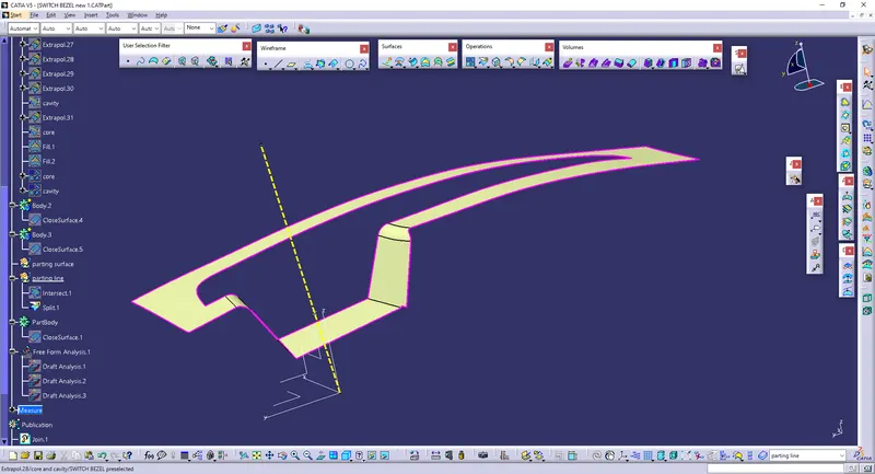
Parting line: It is the line were the component or part and the parting surface meets. In other words, the intersection line between the part and the parting surface is said to be a parting line.
CAVITY ISOMETRIC VIEW
CORE ISOMETRIC VIEW
Conclusion:
The creation of tooling axis, the steps involved in draft analysis of switch bezel, class B & C surface creation, switch bezel solid part creation and core & cavity creation for the switch bezel part were explained in detail with some reference images regarding to the given class A surface of switch bezel and created surface & solid parts.