Week 8 - Challenge 6 - Core & Cavity Design
Week 8 - Challenge 6 - Core & Cavity Design
OBJECTIVE
- Create a Core and Cavity Blocks for the Switch Bezel Plastic Component
- Create Parting surface of the component
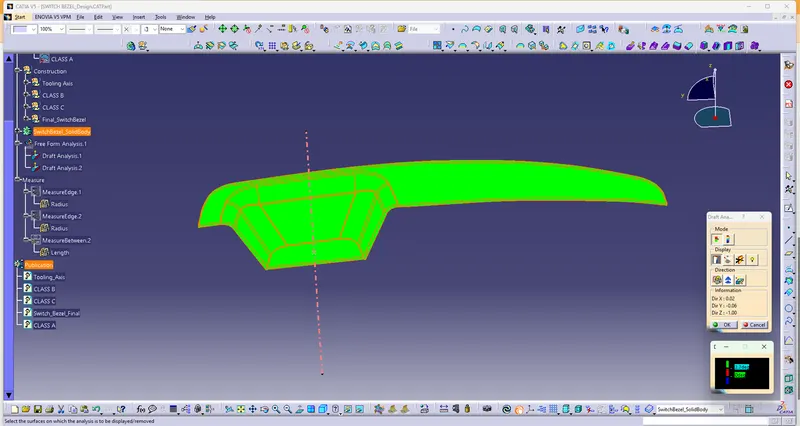
- Analyse the Switch Bezel Component by Featured Draft Analysis
Class A Surface
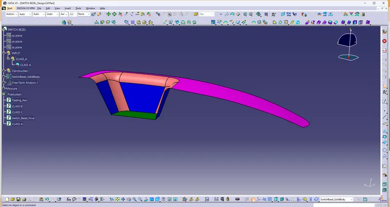
Screenshot of given Class A Surface
Tooling Axis
- From the Given Class A surface, to determine the possible direction of component to draft
- Extract Base of the surface (No propagation)
- Point is created on the base of the surface
- then add Axis System on the ref.point
- Along this axis system YZ direction Positioned sketch as to construct
- Intersection of the surface along YZ direction,inclined Edges of intersection sketch two Lines
- from these two lines create a Bisecting Lines of YZ Direction
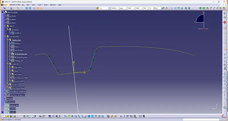
Screenshot of YZ Bisecting Line
- To create XZ direction Bisecting Axis of the surface, by positioned sketch
- Compare to YZ Direction, XZ direction have a one side of face to intersect
- By intersection on XZ Direction, One side of Inclined edges create line and
- then create line on the axis system projection point (Ref.Point) and constraint to the angle of 3 degree from the Intersection line.
- And the line as considered Bisecting Line of XZ.
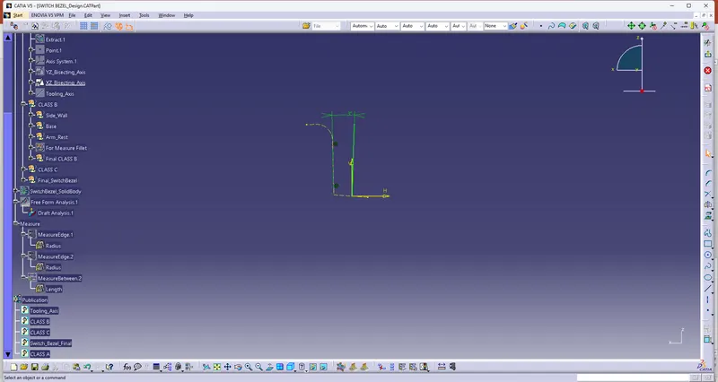
Screenshot of XZ Bisecting Line
- Both YZ and XZ Bisecting Lines, Create Bisecting Line as Tooling Axis of the component to develop Class B and Class C.
- then also Featured Draft Analysis as to derive along this Tooling Axis.
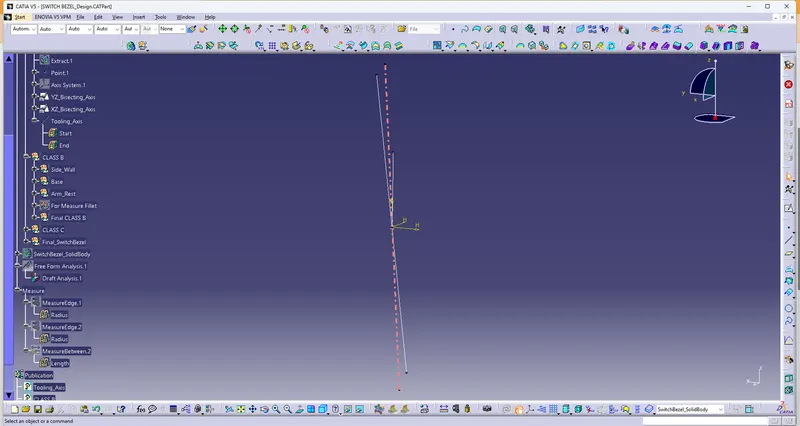
Screenshot of Tooling Axis of the Component
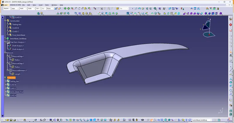
Draft Analysis Of Switch Bezel Component
Parting Surface Creation
- Extrapolate the Class A surface at Point continuity at distance of 15mm
- Extrapolate Class A and Class C Surfaces,Trim Both the surfaces.
- Then Again Trim to Class B surface is Parting Surface with Component Area
- After Intersecting of Join (Class A and C) and Class B,that intersection is Parting Line
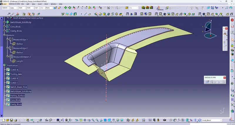
- Then Split Trim (Parting Surface with Component Area) and Parting Line is Parting Surface.
Core Block Creation
- Positioned Sketch, in the Axis System, YZ direction, Draw a Rectangle in Isoconstraint
- Then Extrude the sketch along the direction of Tooling Axis
- then Trim of Extrude with Parting Surface with Component area
- then Close the top portion by using Fill command and Join Both
- Then Closing the surface(In Part Body set) is called Core Block
Isometric View of Core Block
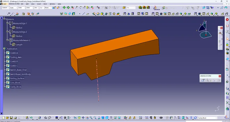
Screenshot of Core Block
Front View of Core Block
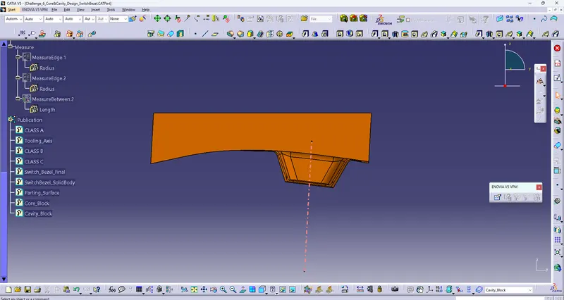
Side View of Core Block
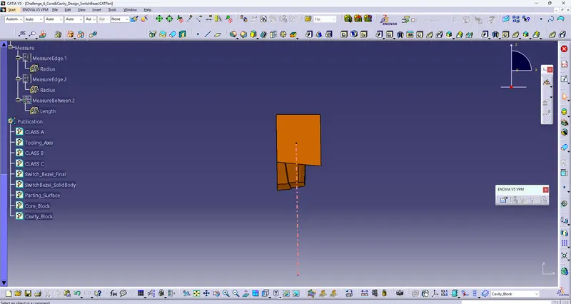
Top View of Core Block
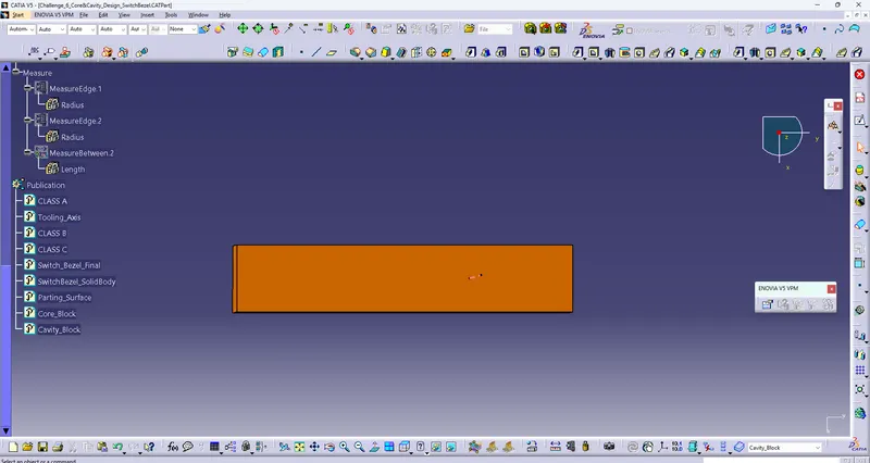
Cavity Block Creation
- Same Positioned sketch is Extrude along the Tooling Axis Direction
- Then Trim the extrude with Class B Surface
- then Close the Bottom portion by using Fill command and Join Both
- Then Closing the surface(In Part Body set) is called Cavity Block
Isometric View of Cavity Block
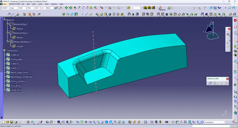
Front View of Cavity Block
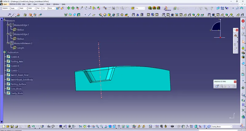
Side view of Cavity Block
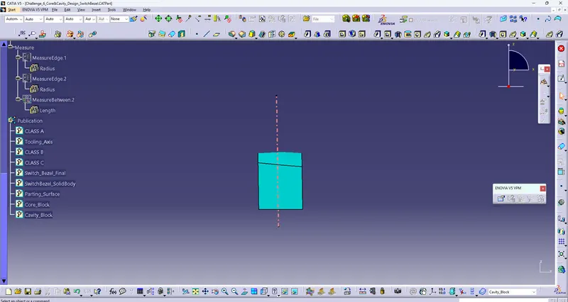
Top View of Cavity Block
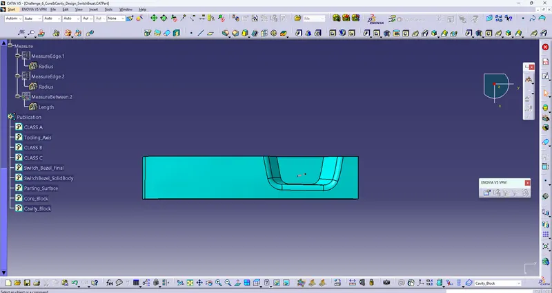
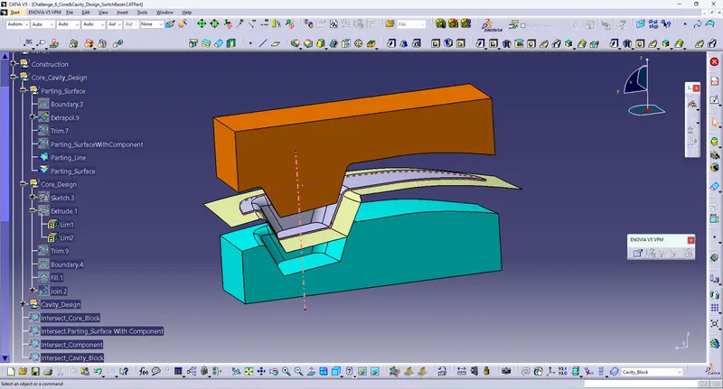
Screen shot of Core and Cavity, Parting Surface and Parting Line , Switch bezel component