Week 8 - Challenge 6 - Core & Cavity Design
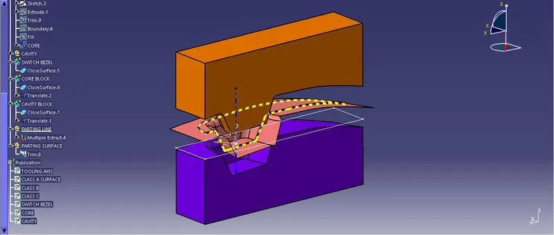
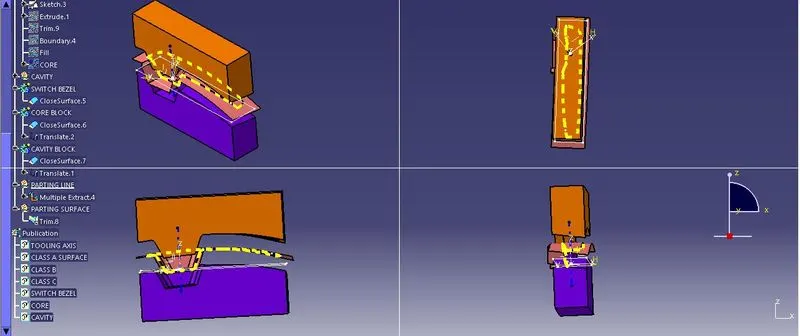
The primary method for sketch analysis is to select Tooling axis at the the centre point in the cup section of the switch bezel by generating bisecting lines from the most vulnerable edges of the walls of the cup. We create it in the shape of plus mark for bisecting. Later, when the B surface is created accordingly and connected with the C surface we come to sketch analysis which is used for analysing whether the B-surface is having minimum 3 degree draft. If all the analysis shows with colour coding is in line with the design norms we go ahead with solid modelling and sketching for industry relevent purpose. The parting is indicated in Yellow dotted lines where the core and cavity meet for holding the molten plastic from spilling and using creating flash. The parting surface is the surface adjacent to the parting line.