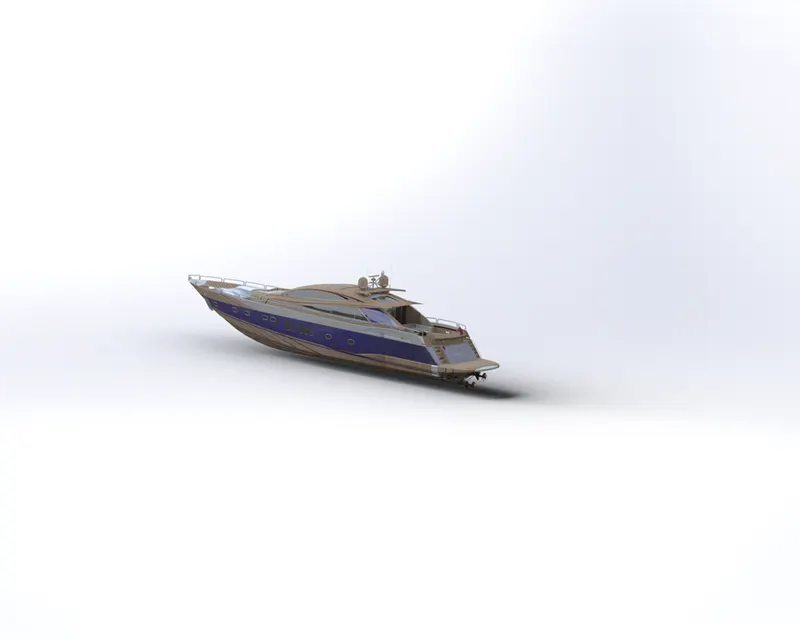
Radar Mast & Final Assembly of Yacht
PROJECT REPORT
MODELLING OF A PREDATOR YACHT USING SOLIDWORKS
BY
VIKAS M
INTRODUCTION
In the pertaining project, we are going to design, model and render an assembled prototype of an Predator Yacht. It is to be noted that our project is completely executed in a modelling software called Solidworks and Solidworks Visualize by which we explore several of its operations and privileges to attain the best possible finish.
SKETCH
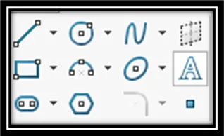
Sketching of Design is a basic step in the modelling process as all the pertaining solids are an expansion or extension of the pre-designed entities. Firstly, we need to select a particular plane suitable for the design process. We then use several of the sketch tools such as line, circle, arc, rectangle, etc., based on given observations and calculations. All of it will be available in the 2D-Sketch toolbar. Lastly, we need to check whether the sketches are constrained(or fully defined), as it helps in achieving inflexible parameters without variables and is very significant to achieve a smooth assembly.
MODELLING
Modelling is a crucial aspect in mechanical design as it converts 2D sketch into 3D entities thereby helping to properly visualize the component. Here there are multiple options and techniques to achieve the above. There are solid metal processes and sheetmetal processes. All of the processes can be manipulated by assigning relevant parameters for suitable designs and henceforth, produce the components. Here we discuss some of the operations used for creating the above design.
Extrude:
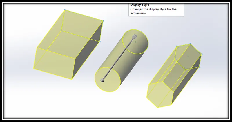
A very commonly used mechanical design entity. Mostly involves normally thickening an enclosed 2D sketch.
Revolve:
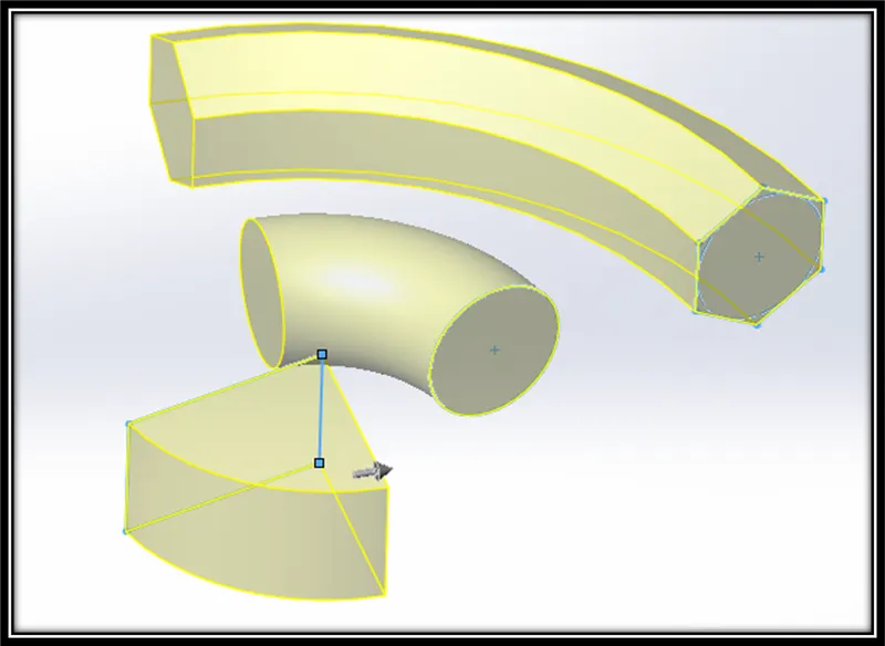
Another operation which helps in achieving the angular thickening of the 2D entities. It helps in mostly circular or revolved entities through an axis.
Sweep:
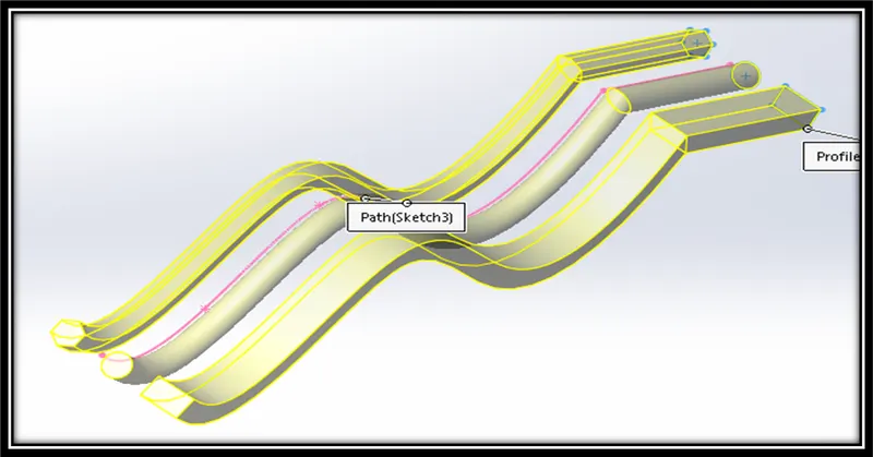
This operation involves creating a solid between two separate sketch enclosures with or without a path to follow. This helps in producing sketches with multiple dimensions and non-straight paths.
Fillet:
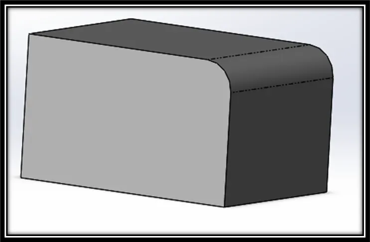
This operation is used to achieve curved edges for a solid body. This helps in increasing the design speed while avoiding sharp edges with a tangential finish.
Chamfer:
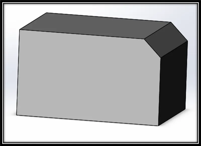
This operation is helpful in getting flat edges or faces by replacing sharp ones. Various parameters such as distance-distance or angle-distance options are available for design.
Mirror:
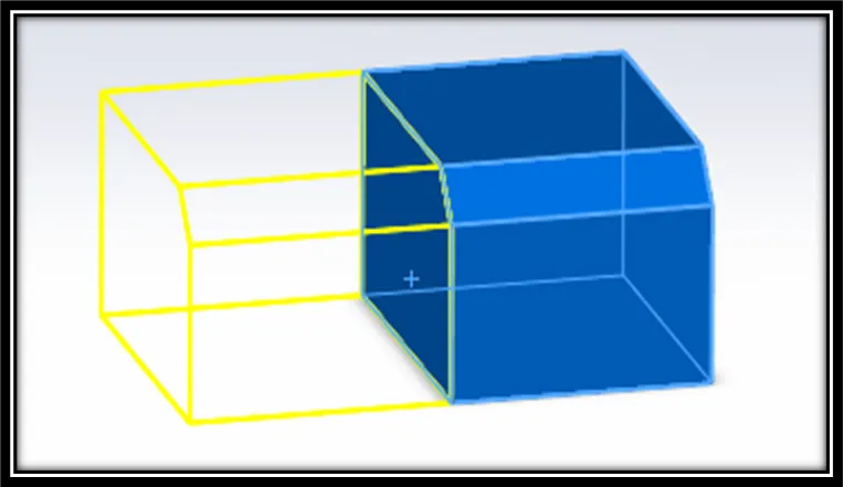
This is an operation wherein copies of a selected sketch or a body/bodies w.r.to a plane is created thereby avoiding redesigning and achieve exactly similar dimensions and constraints as the host body.
Multiple entities:
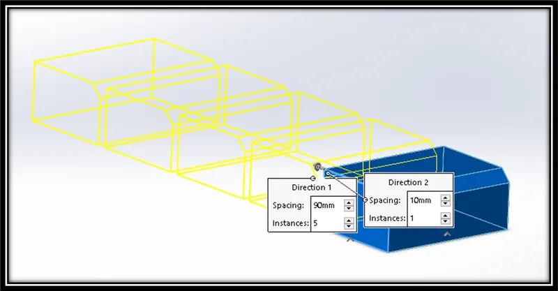
This is an operation similar to mirror but having flexibility to increase the number of bodies w.r.to a path assigned. Various patterns of linear, circular or insert along a path operations will help in achieving the design.
Cut:
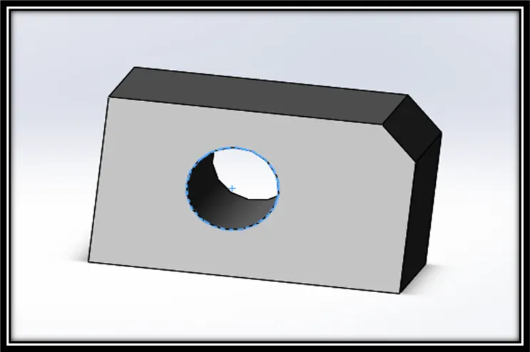
This is an operation used to create deep cavities in solid bodies. Similar to extrude, we can vary our options by which manipulation into linear, circular or design based on a path can be created and help in achieving required solids.
Projected curves:
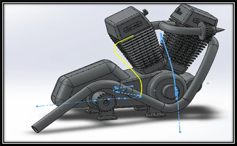
This is a very interesting curve operation by which two different curves in same or different planes is projected to form one curve treading common paths in a separate plane of its own.
FLOWCHART
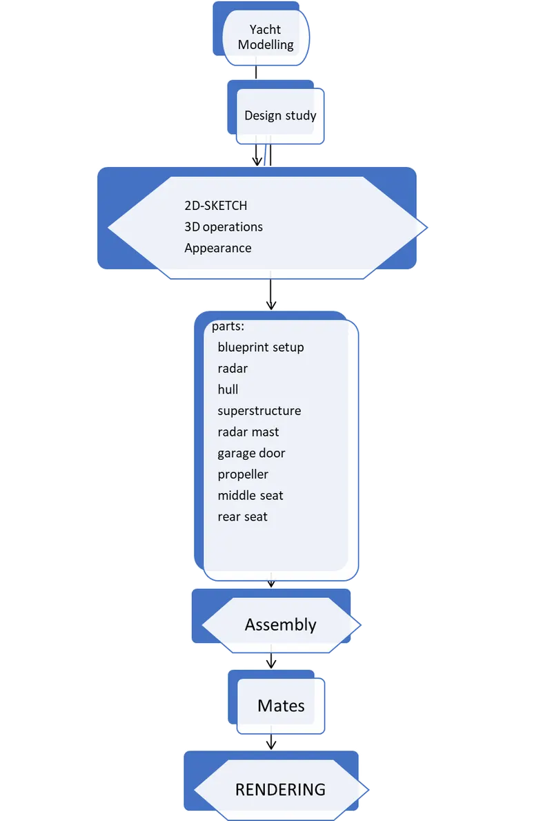
Parts:
Blueprint setup:
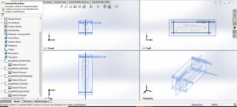
This is the arrangement provided in the five separate planes of the axis wherein a 2D sketch is placed in select coordinates for design tracing and estimates, which thereby helps in speedup of the design process.
Propeller:
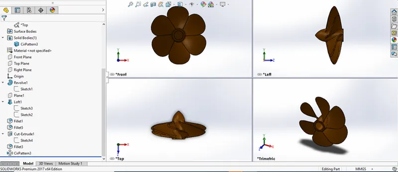
This is the part which provides the backward thrust which in turn gives forward motion. The main principle is turning rotors with angled fins. The design in pretty simple. First the centre protrusion is designed and revolved. Later a loft is created for the fin and a fillet is applied at the sharp edges. We insert the multiple bodies of the fin around the protrusion.
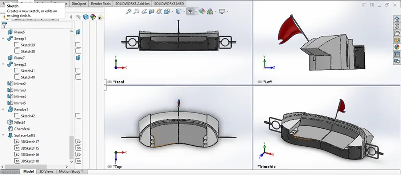
Radar:
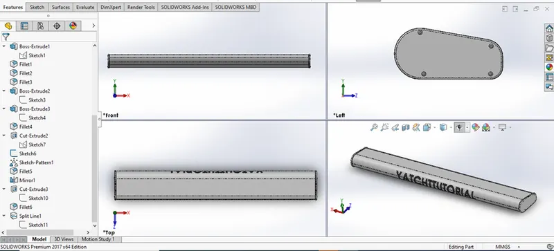
A length of metal box with sides of two pointy edges and an arc is covered on either side for the radar.
Hull:
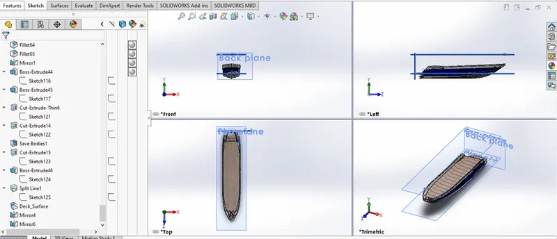
This is one of the 2 sections which divides the yacht into upper and lower halves. This is the lower half which allows the boat to float and contains the propeller system for motion. Along with that it has a deck with railings and anchor attachment. It also contains hollow rooms inside the deck with windows. It even has a garage for storage.
A wide array of operations were done along the blueprint. We used solid operations to sheetmetal operations with surfaces and units. Multiple references for the hull to contain the superstructure was also provided. It mainly involved producing curves with multiple lines or splines or curves itself which traced the blueprint. Rather positioning and producing were all general design operations. Mirroring was done for fast setup after building half the part.
Superstructure:
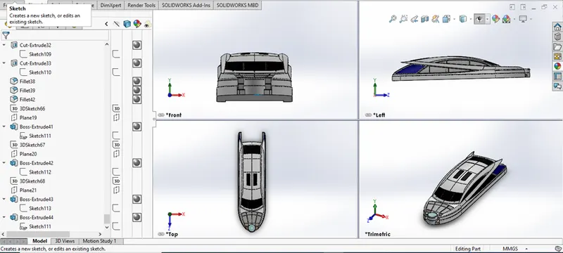
This is the upper half of the boat which contains the roof, riding wheel and several other structures. Many operations of who were used in Hull was used but with different design. The complicated sails and roof curves were made with the help of projected curves and sheetmetal options. Mirroring was done for fast setup after building half the part.
Radar mast:
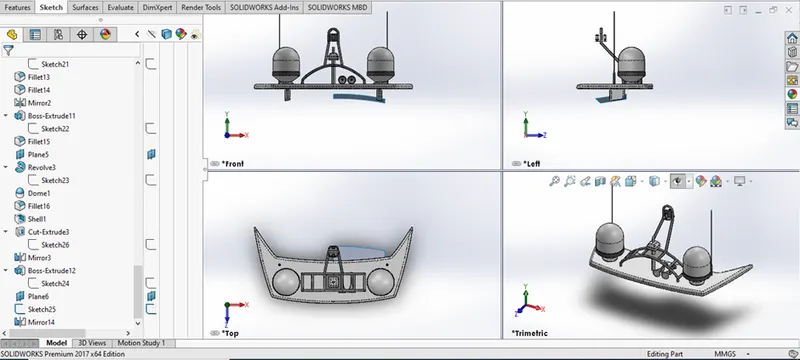
It is rather a small part with several parts. It sits on the top of the superstructure for wireless transmission. Simple revolve and mirror operations were made.
Garage door:
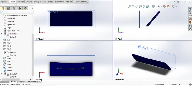
A lift-up door for storage is inserted with both the hinges. Normal operations of boss/base and cut were sufficient for the part.
Front, Middle and Rear seats:
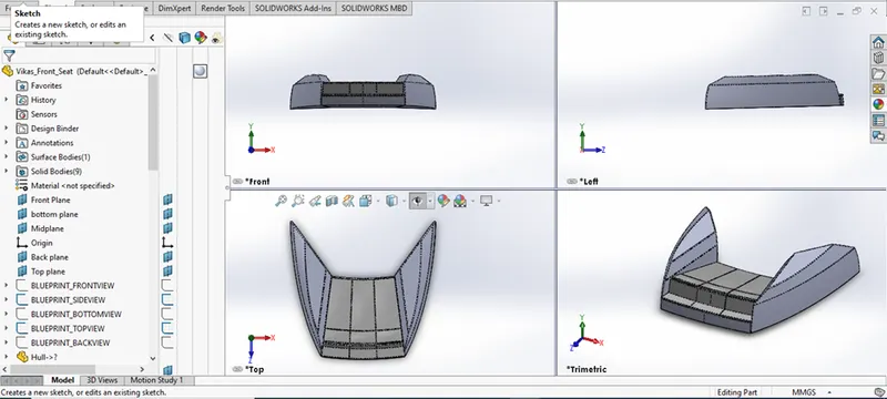
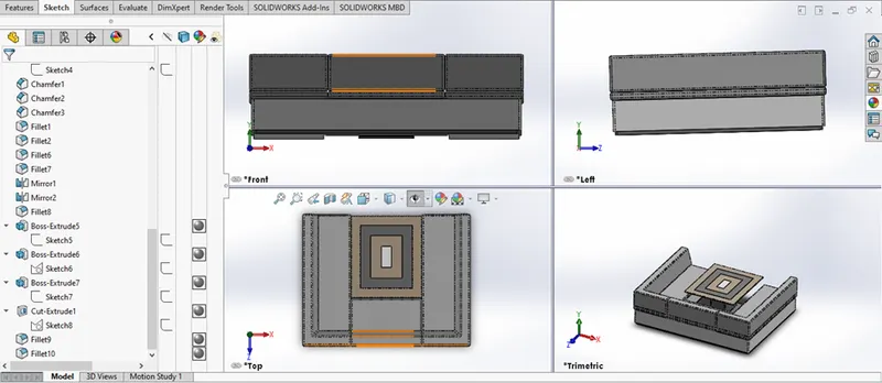
A cushion seat for the deck on three sections was inserted for leisure. Normal operations as above were again repeated.
ASSEMBLY
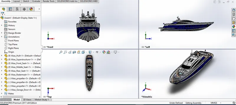
This is a very crucial phase in design where two or more models can be related according to the specified limits and tolerances, where the final product is a fully fledged producible or working component. This method also helps in testing and analysing its design compatibility and knowing whether the foregoing equipment is according to its design constraints.
There are multiple operations we can use, but we will discuss the operations only used in this particular project. All the parts have been created undertaking only Bottom Up approach, so mates are really important.
Mates:
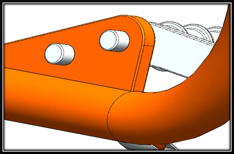
This is the operation where a solid body is related to another body or a plane, so as to fix its positions and use multiple dimensions and relations for assigning freedom of movements with the help of an axis or a plane.
APPEARANCE
This is a crucial operation where a body can be assigned real world properties such as metallic or non-metallic, colour of the body, texture on the surface and many more.
We can also assign the environment around the component and lighting effects on the body suitable for various make-ups and arrangements. This can be easily selected and applied in various lists present in the above option.
SOLIDWORKS VISUALIZE
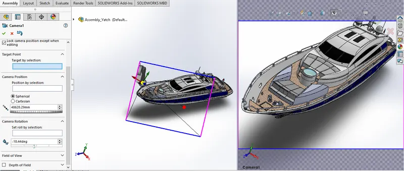
This is basically an advanced version of appearance and camera options present in the normal SW program. Here we have the advantage of achieving a very high definition rendering by assigning multiple frames with a fine finish. We are provided with a number of body and environment options with freedom of synchronizing the range in various aspects. Provided a good Graphics Processor the images or videos can be achieved to have a real world or an animated feel.
Conclusion:
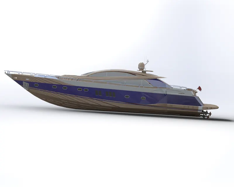
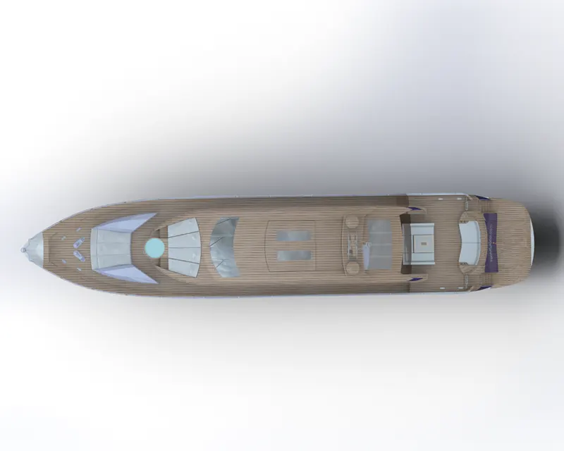
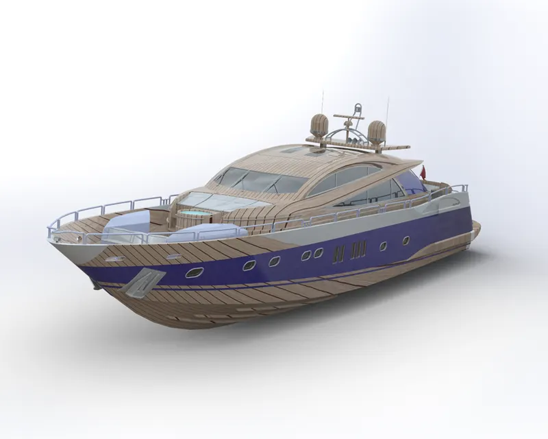
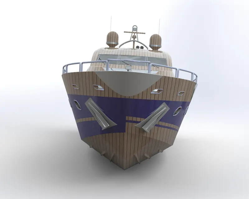
The yacht is designed, modelled and assembled with appropriate appearance and rendered for a realistic look.