Week 8 - Challenge 6 - Core & Cavity Design
Objective:
To create the Core and cavity blocks for the switch bezel designed in the earlier challenge.
Tooling Axis:
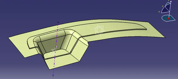
To determine the tooling axis or tooling direction that moulds pull apart in injection moulding, the Class-A surface must first be evaluated. Designing plastic products requires consideration of tooling orientation since it determines the direction of mould separation.
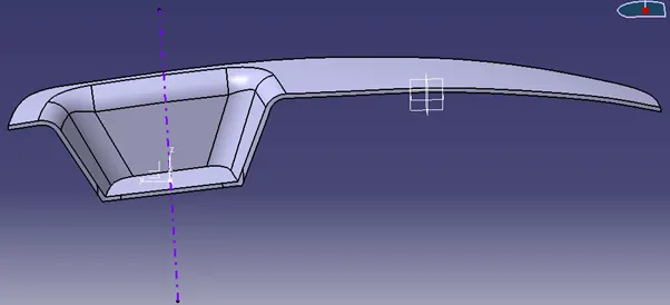
Steps to create Tooling Axis:
- Reference point is first created on extracted surface.
- New axis system is deployed to plot clearance lines.
- The X-direction and Y-direction along the class-A were used to create tooling axis.
- Graphic properties of tooling axis were change before publishing.
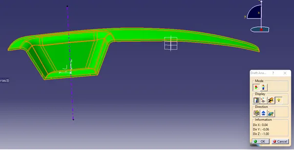
Draft Analysis:
Core and Cavity:
One component of the mould, the core, is in charge of producing half of the moulded part. Actually, the body's core and cavity are its projection and depression, respectively. A mould is created by combining the core and cavity. The plastic material was then injected into the mould to create the plastic component.
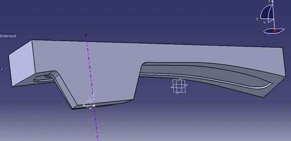
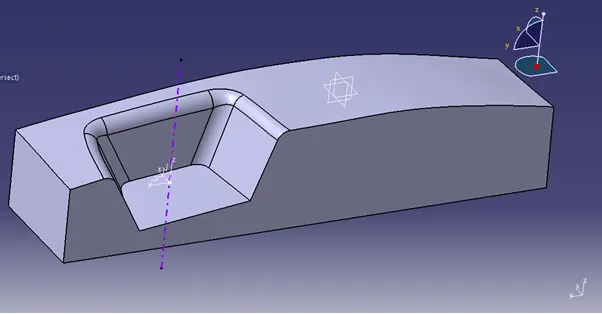
Parting Surface:
The movable and fixed halves of an injection mould are typically its two main parts. During the injection moulding process, these two halves are pressed tightly together to create a sealed hollow and prevent melt flow leakage while maintaining a specific holding pressure. This pressed surface is referred to as the parting surface, and it is typically the largest projection outline of the part.
Parting Line:
It is the area in which parting surface and component meets or it is a junction between core and cavity.
Conclusion:
Hence the core and cavity blocks from the switch bezel we have already designed as the solid part is created successfully. And here we create the parting surface and the parting line. from this Draft analysis and parting surface we try to make the parting surface as flat surface as much as possible which is useful for large number of production the part.