Week 8 - Challenge 6 - Core & Cavity Design
Aim: To create core and cavity block for switch Bezel considering all plastic design rules.
Steps Followed:
- Tooling Axis creation
- Checking Draft analysis for created tooling Axis
- Creating parting Surface
- Creating Core Side
- Creating cavity side.
Tooling Axis:
Tooling axis is the axis in which core cavity open during completion of injection molding. To create the tooling axis, we need the proper orientation or view that gives the correct features and draft available in the component.
Component view from the Z direction gives the proper view for the tool to see the features present in the geometry. To create the tooling axis from the Z direction we need the tooling axis from the X direction since it gives the draft available at the slanted part.
The tooling axis created from the X Direction By the following Steps:
- The class A surface is Extracted
- Then the center point is created using the point, on the base surface at 0mm.
- At the point axis system is created.
- After switching the view of the model to the X direction and creating the tooling Axis.
Using the intersect in ZY plane to get the boundary lines.
Then the lines are created along the slant surfaces.
Then these two lines are bisected to get the tooling axis for the X direction.
- Next switching in the Y direction and intersecting the switch Bezel part in ZX direction to get the intersecting Lines.
- Using the axis center point, a line is drawn in sketch mode and it is constrained at the angle of 6 degrees.
- At last, both the lines are bisected to get the final tooling axis.
Below line represent the tooling axis for surface.
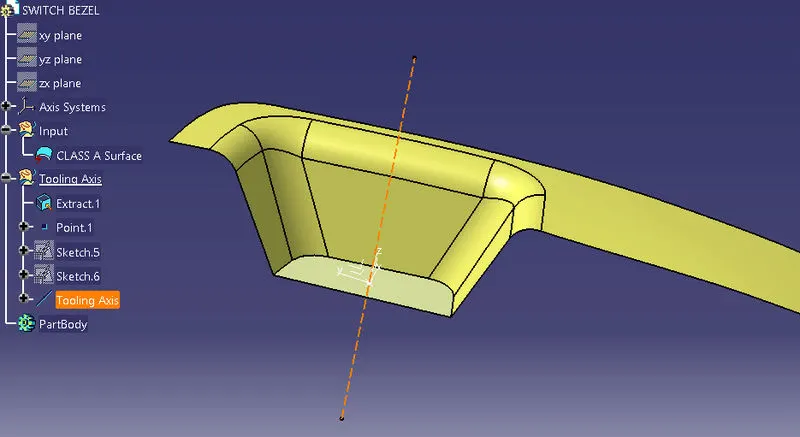
Draft Analysis:
Draft analysis enables you to detect the part we drafted will be easily removed. This type of analysis performed on the base of color ranges identifying the zones on the analyzed element where the deviation from the draft direction at any points, corresponds to specified values.
- Go to insert<analysis< feature="" draft="" analysis<="" li=""></analysis<>
- Click on the compass icon and align it with the tooling axis and click on the surface, we will get our result.
Draft angle dimensioning:
- Typically, one to three degrees draft is recommended.
- For untextured surfaces, generally a minimum of 0.5 degree draft per side is recommended.
- For textured sidewalls use an additional 0.4 degree draft per 0.1mm depth of texture.
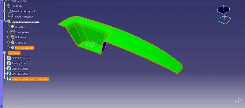
Parting Surface:
Generally, injection mold has two major components: the movable halves and fixed halve. During injection molding process these halves are pressed tightly from a sealed hollow to avoid the melt flow leakage and maintain certain holding pressure, the pressed surface called as parting surface, usually parting surface is the biggest projection outline surface of the part.
Parting surface design directly affects the product quality, ease of construction and operation of the injection mold.
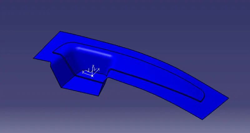
Parting Line:
Parting line are where the two halves of the mold meet. This generally create a physical line on a part that is both visible and noticeable to the touch. These lines however can be hidden or minimized when placed along edges of the part. It is represented by dotted line in the below picture.
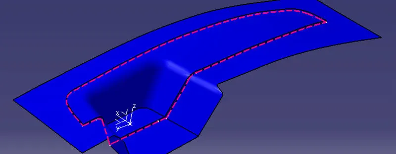
CORE :
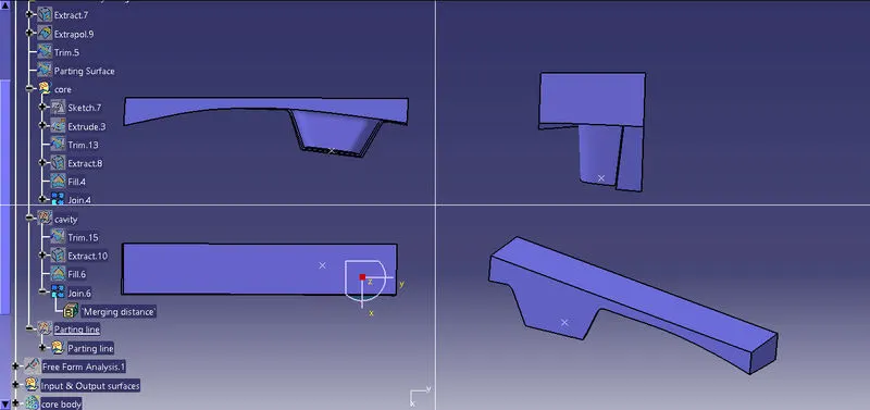
The core design is started with extracting the parting surface that becomes the datum for the core and cavity. Extract the A surface and C surface and trim with extrapolated B surface.
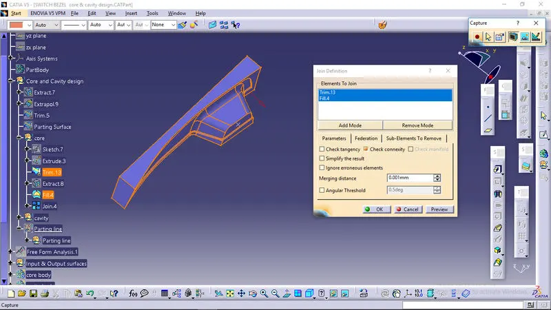
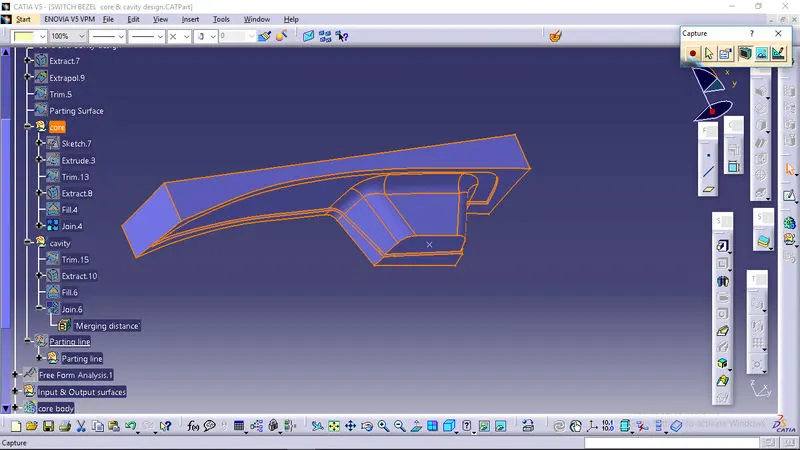
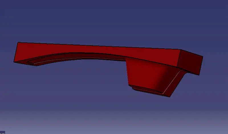
The achieved surface is converted to enclosed rectangular box by extruding rectangular profile at a distance from the parting line along tooling direction. Hence it is closed and joined together to form closed surface which is converted to solid body in part model.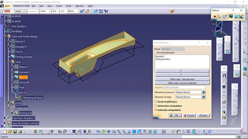
CORE CLOSE SURFACE BODY:
ORIENTATION:
CAVITY:
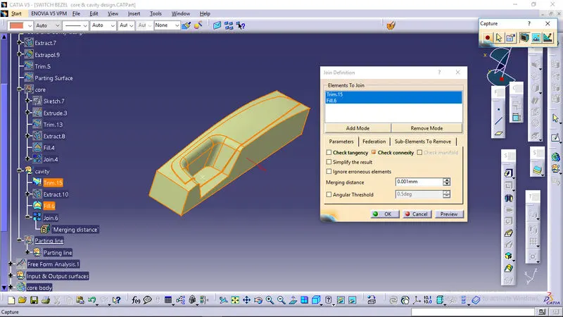
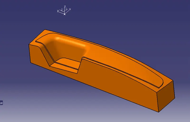
The cavity is the part where the injector and filling of the molten plastic happens. The cavity block is prepared by trimming extrapolated B surface and same profile used in core for rectangular block to extrude along the tooling direction.
The achieved surface is filled and joined to create closed surface as shown picture.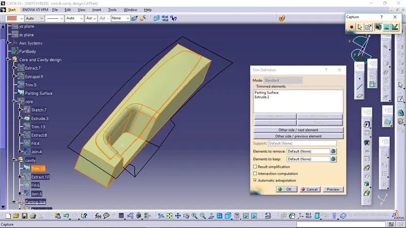
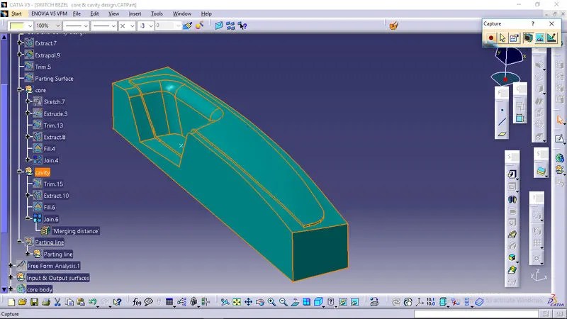
CAVITY CLOSED SURFACE BODY:
ORIENTATION:
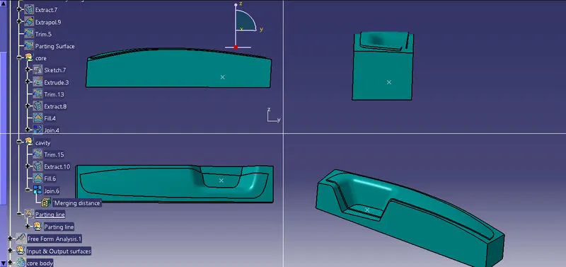
Core & cavity with mold component and parting surface and parting line given below,