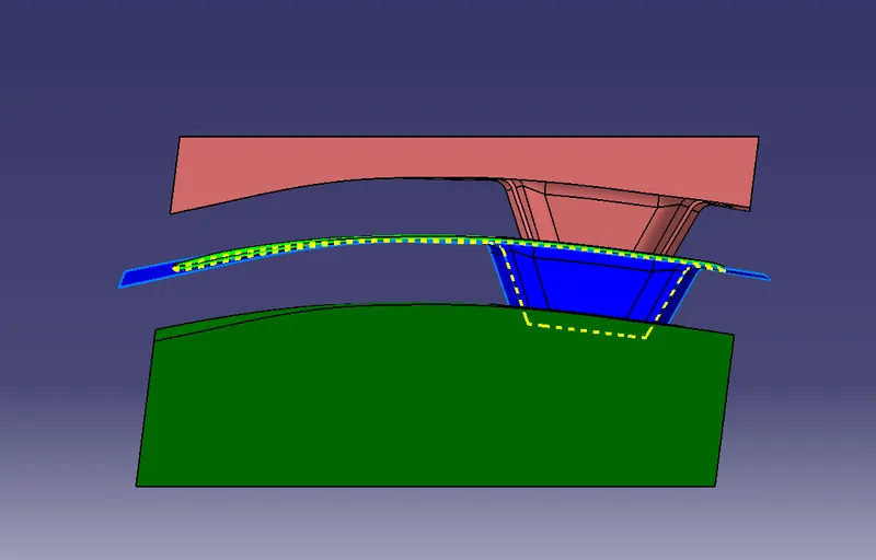
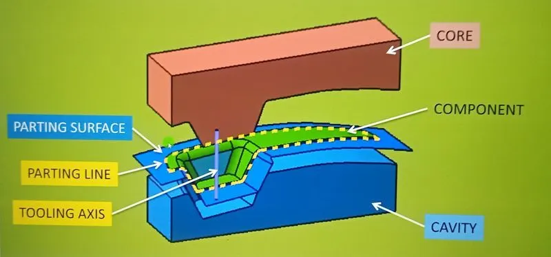
Week 8 - Challenge 6 - Core & Cavity Design
Objective: The main objective of this challenge is to design a Core and Cavity for a Switch Bezel' in CATIA V5 with the help of a surface workbench.
Before we design the core and cavity, we should perform a draft analysis on the solid part body of the switch bezel.
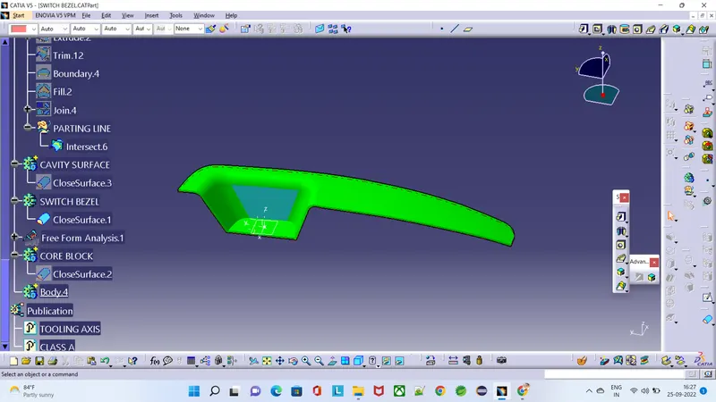
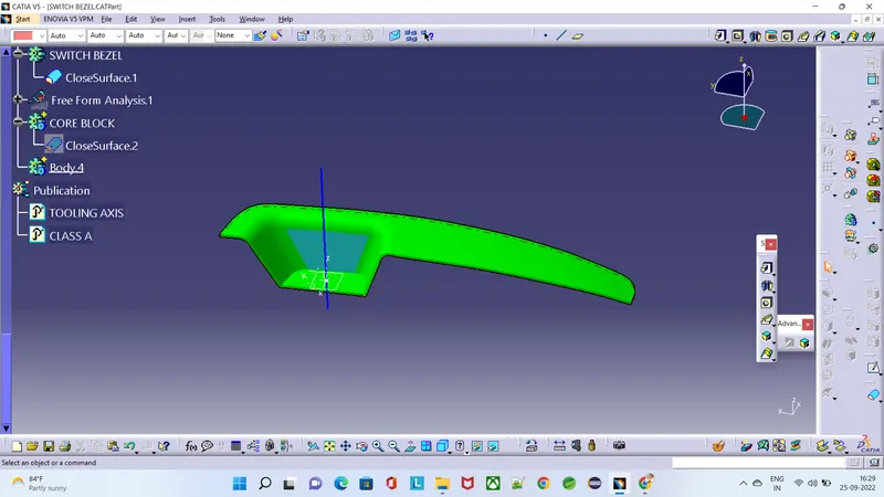
Core Design: - Initially, I have taken the boundary of the class A surface to extrapolate it. After extrapolating the class A surface I trimmed extrapolated class A surface and class C surface (join of class A and sweeped surface), after I trimmed the class B surface with Trim.5 to create the 'Parting surface'. Now I draw a rectangle, which does not exceed the boundary of the parting surface.
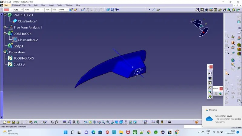
Now I extruded the sketch along the tooling axis, after extruding the rectangular sketch I trimmed both the parting surface and rectangular extrude to remove the lower side of the parting surface. I filled the upper surface to make a closed surface by joining the filled and trimmed surface. Now I make the closed surface into a solid body, the obtained solid part body is our CORE bock.
- Extrapolated class A surface
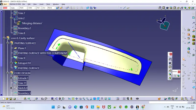
- Trimming the class C surface with extrapolated class A surface:
- Parting surface trim:
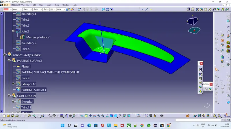
- Rectangular sketch to extrude:
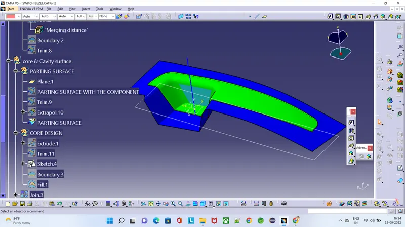
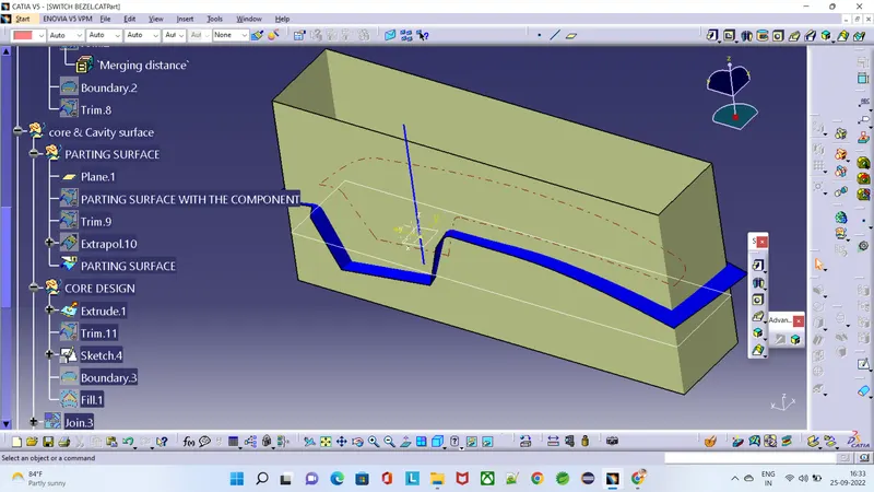
Trim for Core block:
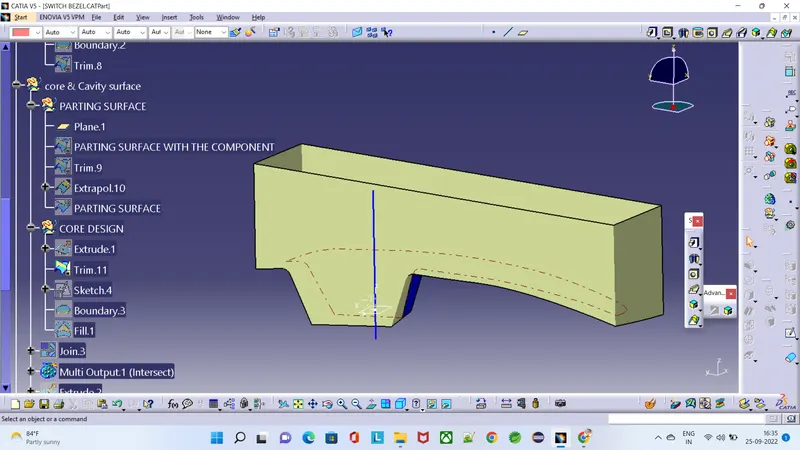
- Core block:Fill it & making it to Closed surface:
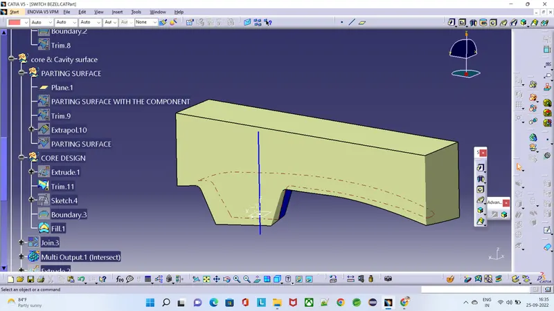
Core block solid:
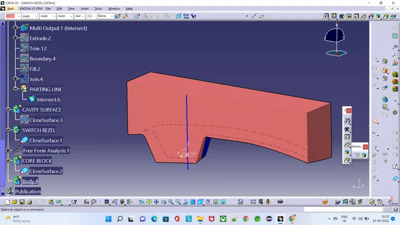
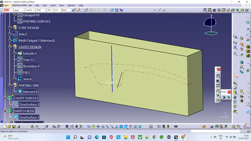
Cavity Design: - To create the cavity block, I trimmed the rectangular extrude with a class B surface to remove the surface which is the upper side of it. After that, I filler the surface which is opened, to make a closed surface by joining both trim and filled surface. Now create a solid body from the closed surface by using the closed surface. The obtained part body from the closed surface is our CAVITY block.
- Trim for Cavity block:
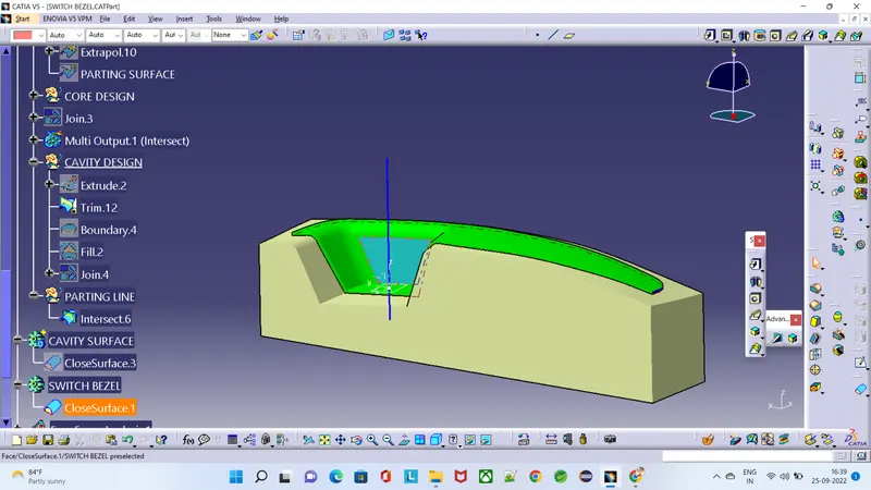
Core block:Fill it & making it to Closed surface: 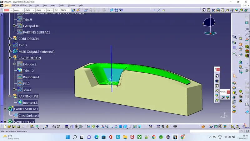
Core block solid:
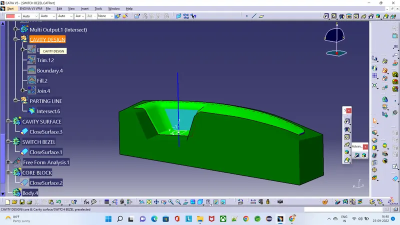
- Instersect the body & see how they joining
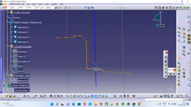
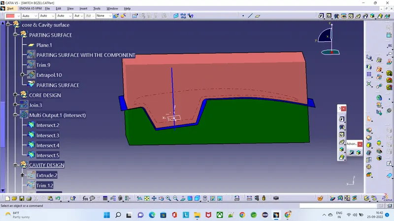
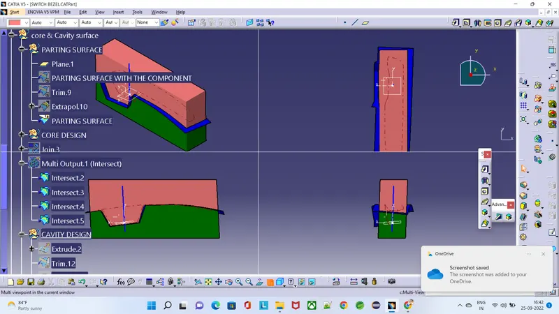
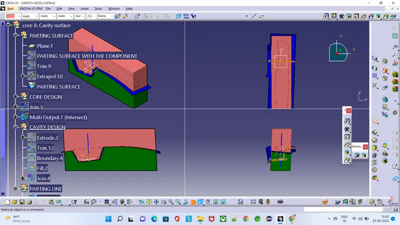
- side & T0P VIEW OF CORE & CAVITY SURFACE
- TOP VIEW
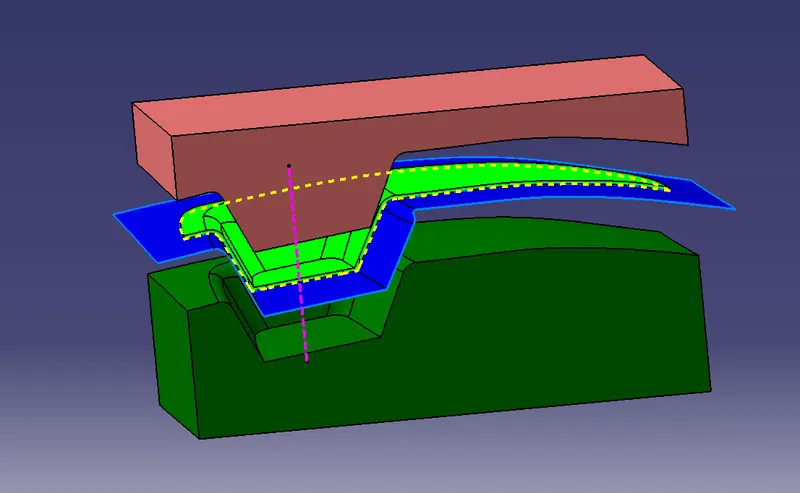
- SIDE VIEW