Week 8 - Challenge 6 - Core & Cavity Design
AIM:
- To Create the Core and cavity blocks for the switch bezel component.
DESCRIPTION:
1. CREATING TOOLING AXIS -
The Tooling Direction is basically the direction that the mold pulls a part. The mold is built in two separate pieces, basically. You have a Cavity side and you have the Core side. The Core pulls apart from the Cavity and that's the Dye line or the Tooling Direction.
- Open the given CAT part file.
- Check for gaps between surfaces for that click on join and then preview.
- If theres any gap between the surfaces join them with a maximum tolerance of 0.003 mm.
- Extract the boundary and dissemble the boundary.
- Find the correct tooling axis where the material don't interfere with the tooling axis and all the elements can be created.
- Create an axis system using at the centre of the switch Bezel.
- Intersect the yz plane with respect to the class A surface.
- Hide the class A surface and create point to point lines on the suspected drafts.
- Create bisecting line with the two lines and point to create a tooling axis.
- BISECTING LINES were used to get the exact medium from the two sides so that maximum positive draft angle can be achieved.
- The tooling axis is created for the component by bisecting two axis from x and y planes.
2. PUBLICATION
- Publication is done to the component to make it visible and navigate easily.
- To publish the component go to tools > publications and then select the tooling axis and the class A surface.
- A separate tree structure is formed under the main part.
3. PARTING SURFACE
- Generally injection mold has two major components : the movable half and the fixed half, during the injecction molding process, these two halves are pressed tightly from a sealed hollow to avoid the melt flow leakage and maintain certain holding pressure, the pressed surface are called parting surface , usually parting surface are the biggest projection outline of the part.
4. PARTING LINE
- A parting line is an inevitable part of injection molded products.
- It is the line of separation between where two halves of a mold meet.
- It manifests itself on injection molded parts as a line that runs the entire perimeter of the part.
- In most parts, it is just a line that runs straight down the middle.
5. CORE DESIGN
- Core - A portion of the mold that goes inside a cavity to form the interior of a hollow part.
- Core-cavity - A term used to describe a mold created by mating A-side and B-side mold halves.
x
6. CAVITY DESIGN
- A mold is a hollow form typically made from stainless steel that has plastic injected into it to manufacture a plastic part.
- The plastic is inserted into the mold cavity, which is a hole in the mold shaped like the desired part.
7. 3D VIEWS
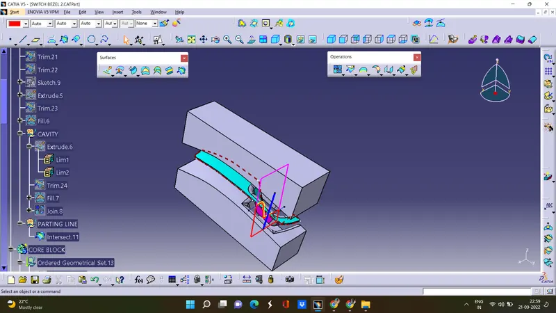
- ISOMETRIV VIEW
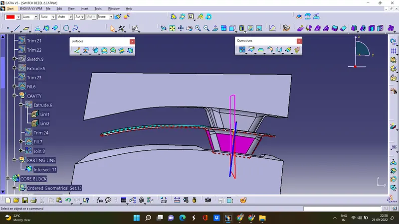
- FRONT VIEW
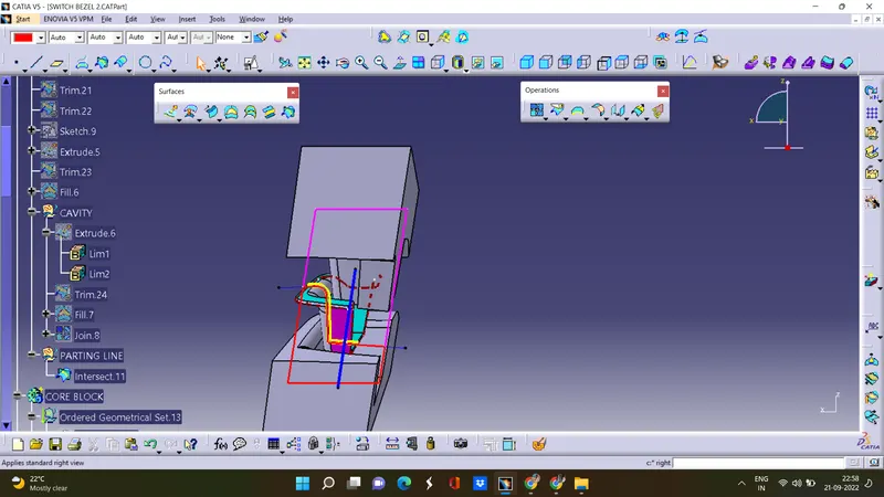
- BACK VIEW
CONCLUSION:
- The Core and cavity blocks for the switch bezel component is created.