Week 8-Challenge
Objective:
- To generate 3D mesh on the given components and should pass all the given quality parameters.
Procedure and result
- Geometry cleanup
The given 3D CAD models are imported into Hypermesh. To separate the components from the assembly. We can use
Tool-> Organize -> surfaces (select attached and click on housing surface)
to move surfaces under a new component name.
It is now checked for CAD errors using visualization tool. Change visualization to “By Topo” and switch to wireframe mode to view the status of each edge.
We also see some edges on the model which are very close to each other and would create problems while meshing (elements would fail because of minimum element length requirement). Toggle unnecessary edges using
Geometry -> Quick Edit -> Toggle edge
In these components, we can see areas where edges are very close and would eventually fail quality criteria if meshed. So, it is better to toggle these edges.
We can also use Auto Cleanup option to clean the geometry
Geometry-> Auto Cleanup
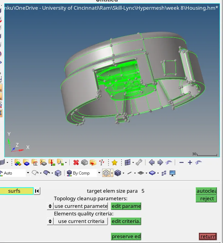
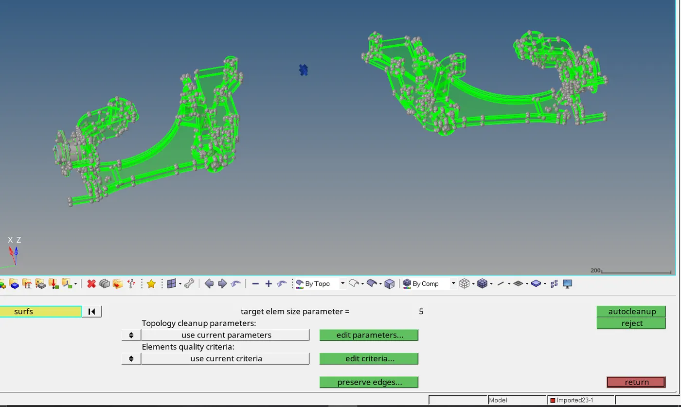
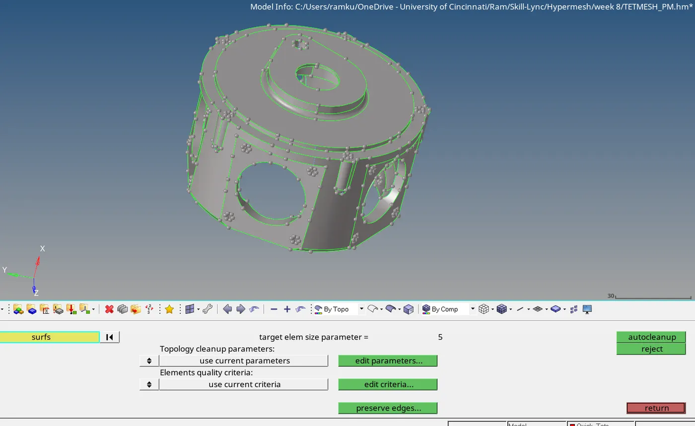
The component transparent in green tells the component consists of only Solids whereas the other has surfaces.
To create 3D tetra mesh from 2D trias, only having surfaces is better.
To create 3D volume tetra, solids are necessary.
- Meshing
The given quality criteria is set in the
Menu bar -> Preference -> Criteria File setting
we will mesh the components individually using the quality criteria provided
For Housing model
Elements sizes: Min- 2mm, Target- 5mm, Max- 7mm
Tet collapse: 0.15
For model 2 and model 4
Element size: 6mm
Tet collapse: 0.15mm
For components having surfaces
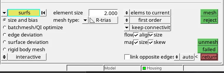
Components are automeshed using appropriate length and in the automesh option, flow – align and size are checked. Mesh type is changed to trias
It is better to split the surface into smaller rectangles as much as possible to have smooth quads on the surface.
Geometry -> Quick edit -> Split surf-node or Split surf-line (Node to Node or Node to Line)
On fillets/hem regions, it is advisable to capture the high points on the fillet. In order to capture the high points, create a Mid line between the boundary lines of the fillet.
Lines -> Midline

Create nodes/points on the Mid Line
Geometry -> Quick Edit -> Add points on Line (Qty:3 – if given 3, two points will be on the endpoints and one will be created on the midpoints of the line)
Geometry -> Nodes -> Extract parametric (Number of u nodes:3)

Now we can split the fillet/hem region using
Geometry -> Surface edit -> Trim with free lines and N1,N2,N3 and toggle the boundary lines of the fillet so that mesh quality error due to minimum size criteria can be avoided.

2D -> Automesh
Symmetric components are split into two along the symmetric line. Only one surface is meshed and the other surface is meshed by duplicating and reflecting the elements on the meshed surface.
Now to convert into 3D testeamesh, go to
3D -> tetramesh -> Tetra mesh -> Fixed trias/quads to tetra mesh
And select all the elements

Check Tetramesh parameters and set Tet Collapse to be 0.2

Select the options
Fill voids, fix midnodes and smoothing
And now go to Tetramesh and mesh
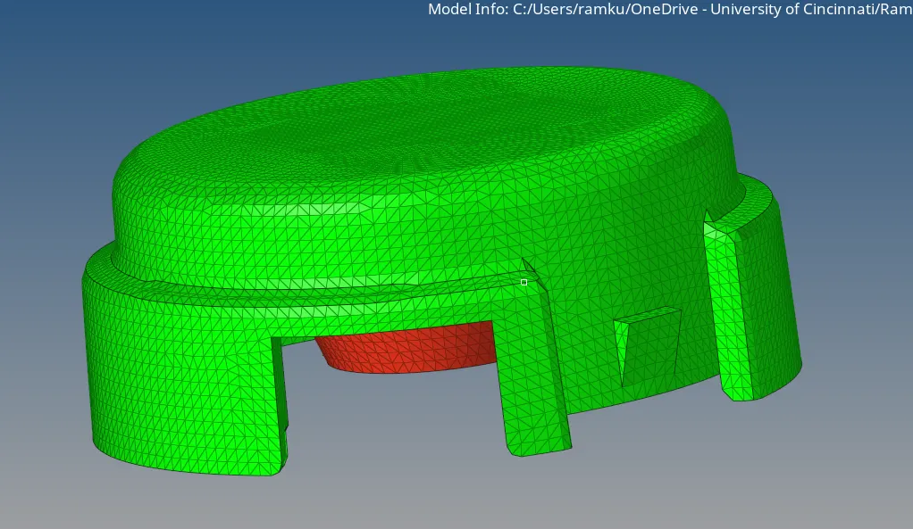
For components with Solids
3D -> Tetra mesh -> Tetra mesh parameters -> SET PARAMETRS
Now go to Volume Tetra option and select the solids and click mesh

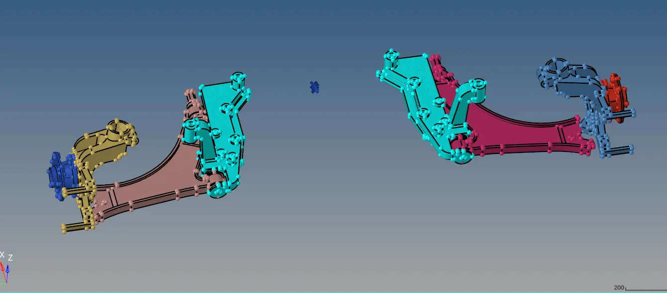
We can mesh only one side of the assembly and then elements can reflected to other side of the assembly
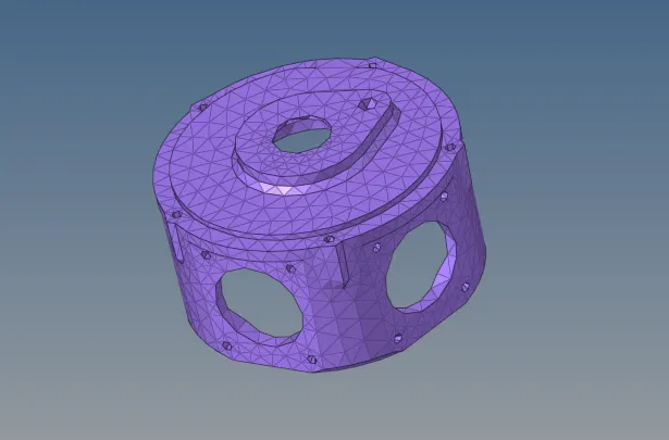
While checking for quality paramets, if some elements fail, we can use Tetra remesh option.
Commands under 2D -> Quality Index
Node optimize
Element Optimize
Place Node
Split quad into trias
Combine trias to quads
Drag Tria
Swap Edge – used to swap edges of tria elements on surface edges

Checks
Tools -> normal
To ensure all the element normals from one side of the surface point in one direction
Tools -> Penetrations
To ensure there is no penetration of elements
Tools -> Dependency
To ensure there is no element dependency
Tools -> Edges
To check connectivity of elements. If there are disconnections, equivalence it
Menu bar -> Mesh -> Checks -> Comparison – to check how well the meshes match with the surface. If there are not matching, we can use Project command to project elements/nodes onto the surface/edge.
Finally, after performing the above mentioned procedure for all the 2 components in the Housing model, the quality of the mesh is checked using
Tools -> 2D -> check elements
Min length: 2mm
Max length: 7mm

Tools -> 3D -> check elements
Tet collapse: 0.15mm
