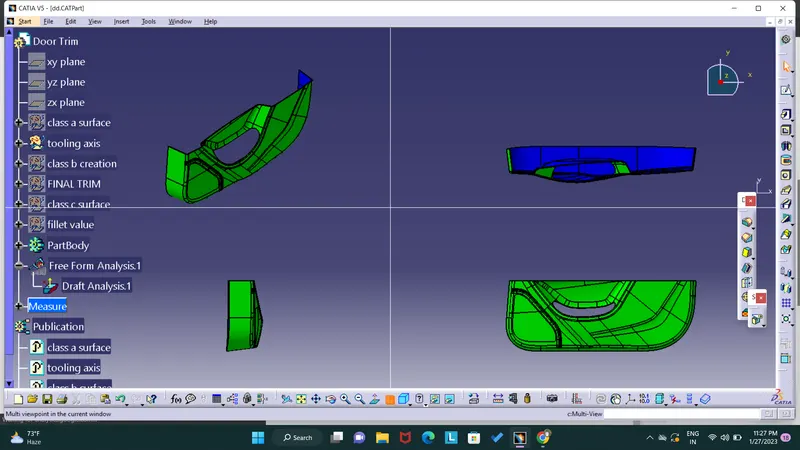
Week 8 - Challenge 5 - Door Trim Lower
tooling axis creation:
TOOLING direction:
tooling direction is basically a direction that the mould pulls a part , the mould is builld in to two separate pieces part,basically you have a core and cavity part . core part is used to create a class a surface . and cavity part is used to create class b surface , when the core and cavity parts puss together using hydraulic or pneumatic press to prodce the component . the class c surface is intermediant part is pressent between class a and class b surface . the class c surface also prodused by core block .
TOOLING AXIS :
tooling axis is used to define the flow of mold direction.
TOOLING AXIS CREATION:
Methods of tooling axis creation :
biseting method
onsurface creation
xyz plain to create
pick the compass place on the component and rotate it
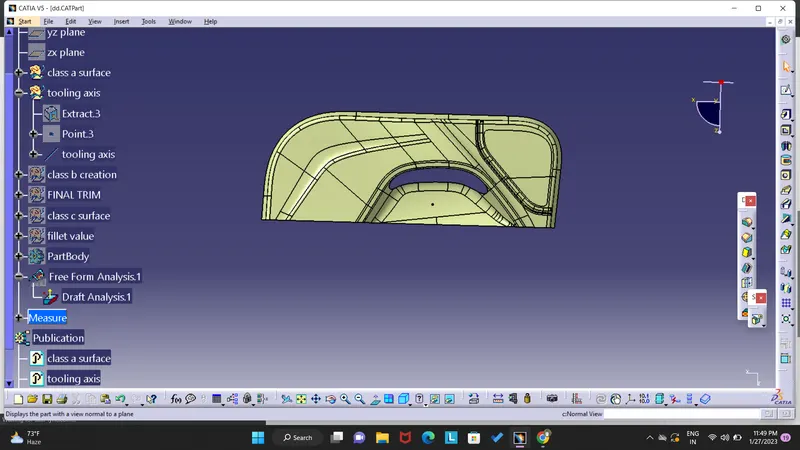
inthis part using onsurface method to creating the tooling direction. insert a new geometry set and select the proper position of the face useing extract option to select the face .
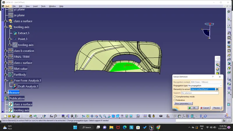
select the point option to creat the point on center .
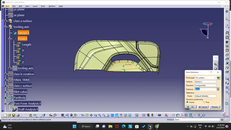
using line option to draw the perpendicular line
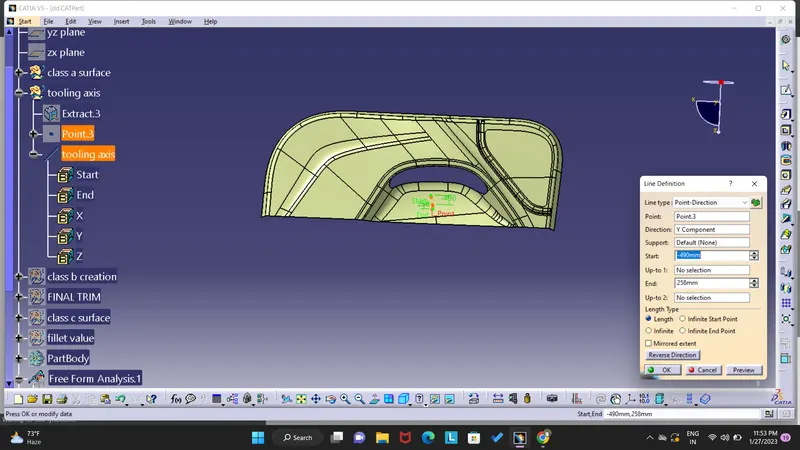
after creatin the line now the line is known as tooling axis , we need to check the line so select the line click normal to view option its show like this then your tooling axis is good .
DRAFT ANALYSIS:
The draft analysis technique is used to analyze whether our part model created in cad is manufacturable based on the draft condition applied.here the part should get easily removed from the mold. no parts can be ejected ftom the tool if it is having a straight 90 degree profile from its base surface . a small draft angle is provided to each and every area of the component in order to get easy removel of the component from the tool.
the draft analyse technique is used to analyze whether our part model created in cad is manufacturable based on the draft condition applied. hear the part should get easily removed from the mould. no parts can be ejected from the tool if it have a straght 90 degree profile from its base surface . a small draft angle is provided to each and every area of the component in order to get eassy removal of the component from the tool. plastics component miniumam draft angle is 3degree . the draft angle is vary for defferent metarials.
CREATION OF DRAFT ANALYSIS:
STEP 1 :
go to customize view perameter and click the view mood perameters then the view mode customization will be present and go the mesh option to select the material.we not select the meterial option unable to do the draft analysis so its must impartent.
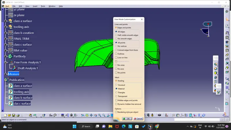
STEP2:
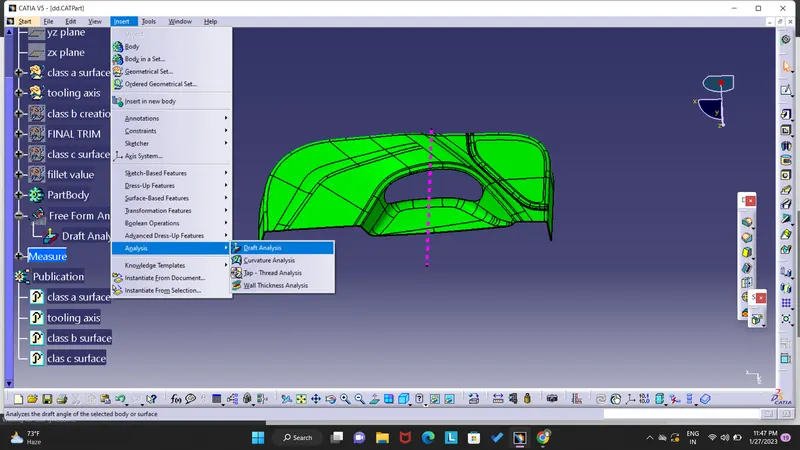
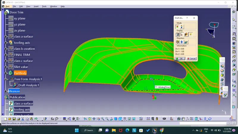
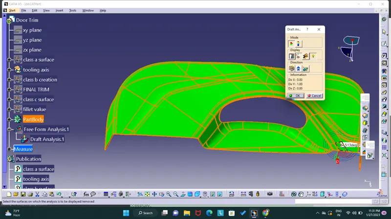
go to insert option to select the analyse option and select the draft analyse option.now you see the two windows . one window is containing mod display direction information and another one is containing color scale variation. using mode option to select the analyse mode quick and full analyse mode.using display option to change the colour and find out the draft angle any paticular point and light ajusement , display option contain compass and lock icon and draft direction anf final option shows the xyz distance of the the companent any point . the second window only have the coluor code . there three types of colour will be present , green and red final one is blue. green colour indicate above 3 degree draft angle and blue colour indicate below 0 degree draft angle and rde colour indicate less then 3 degree draft angle.
pick the compass and drag it tooling axis and lock the compass and select the draft driction icon click on the component surface .
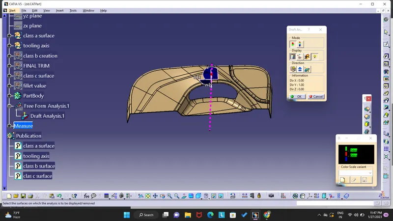
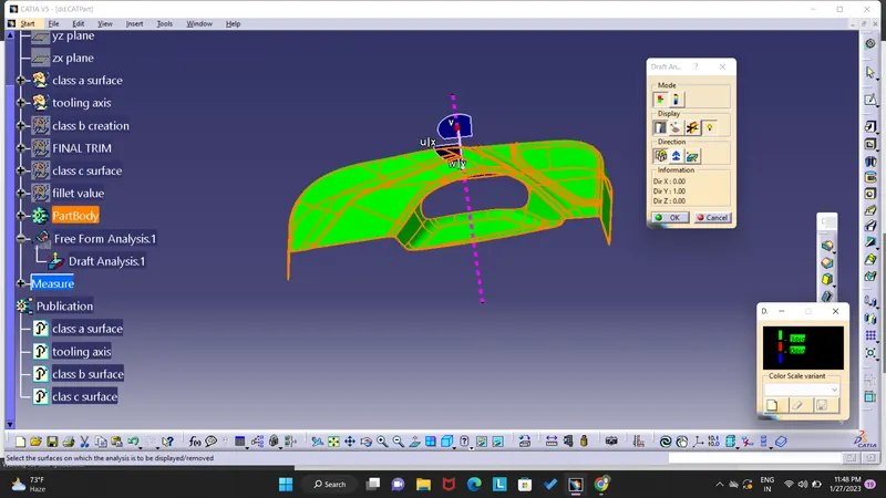
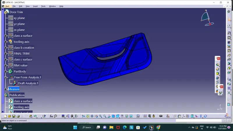
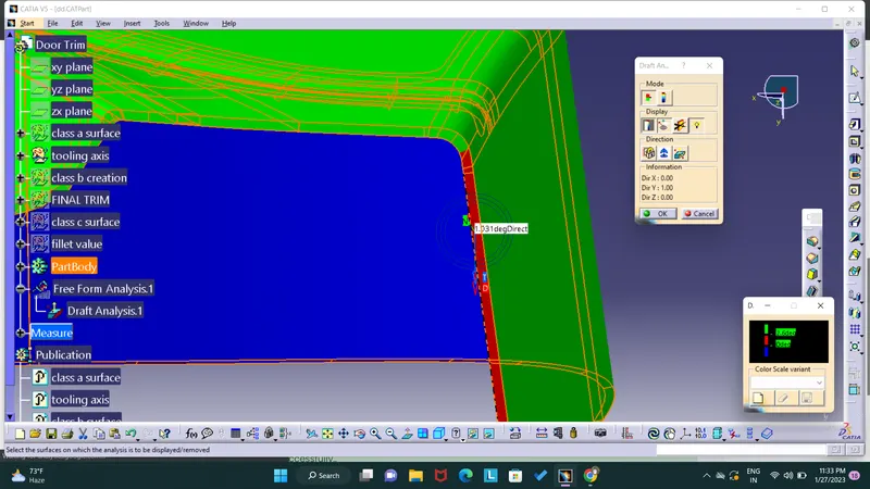
in this component red colour shows the two areas so we try to reduse the draft angle 2.9&2.8&2.7&2.6&2.5&2.2& nothing will be change so we inform to the class a designers to modify the class a.
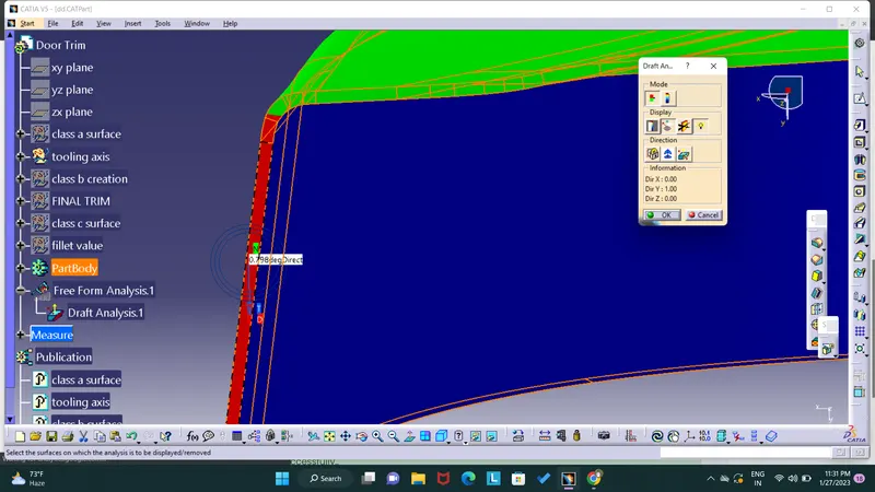
class a draft analysis:
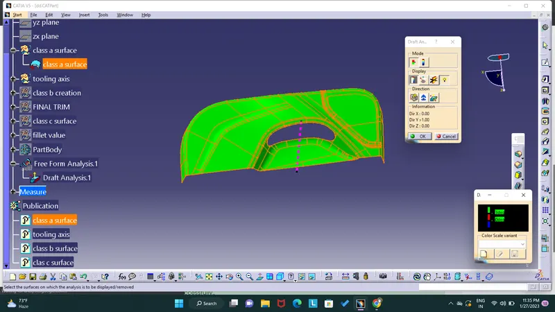
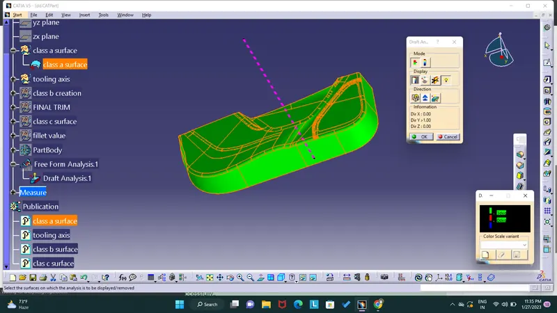
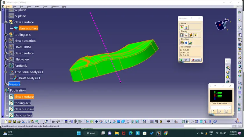
final component draft analysis:
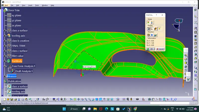
solid model screenshots: