Week 8 - Challenge 5 - Core & Cavity Design
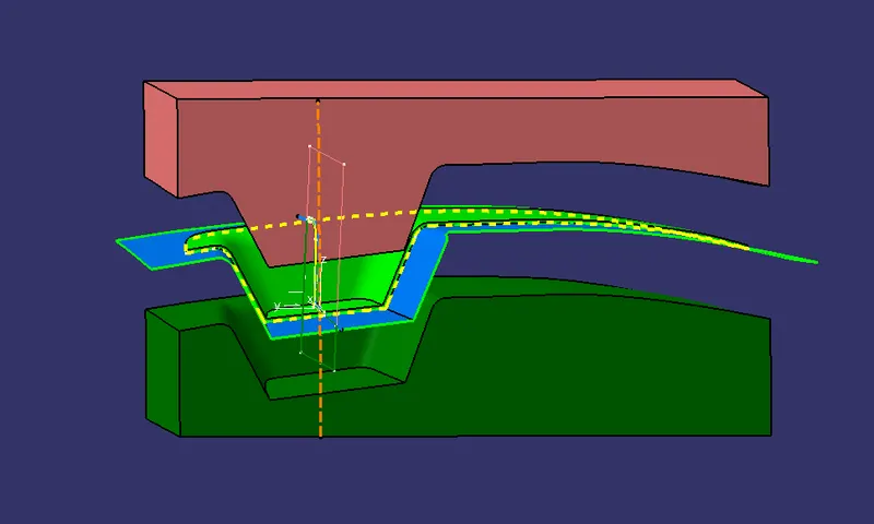
Tooling Axis creation
- Create an axis system and a point at the centre. The axis system should be similar to the part body axis system.
- By using intersection command on surface workbench create an intersection between XZ plane and the fan cover surface.
- After that create dummy tooling axis by using Point and Direction which passes to through the previously created point.
- Create a lines by using pionts on faces which you think will be create issues. Make sure this points will clear the dummy tooling axis.
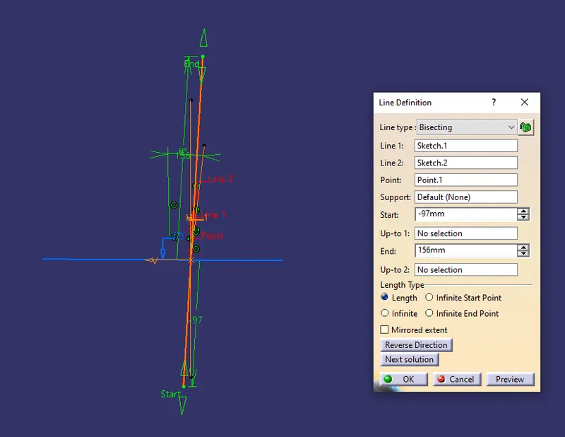
- Now create a line by using bisecting line command which is line feature and select those two lines which are passing through the faces. This bisecting command will create a mid line b/w this two lines and name the bisecting line tooling clearance line in X direction.
- Repect the same step for YZ pane for fan cover and create tooling clearance line in Y direction.
- By uing this X direction line and Y direction line create a bisecting line b/w them and name as tooling axis.
Draft Analysis
- In Drafting Analysis first have to check the given class A Surface joined r not.
- Next create a tooling axis as explained above.
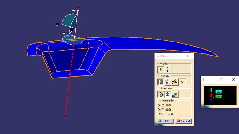
- Go to instert>>Analysis>>Feature draft analysis.
- Make sure that in customize view parameters command in shading it has to be in material status.
- Now drag the red coloured point on the compass to match the tooling axis which we have created.
- Then click on the lock icon under the display command and a point will appear on your screen and top the point on the surface of the fan cover.
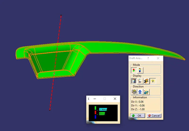
- Change angle degree to 3 Degrees and lick on ok.
Tooling Axis :
Draft analysis :
Class A-surface
Final Component :
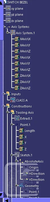
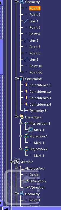
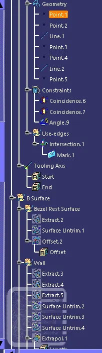
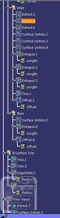
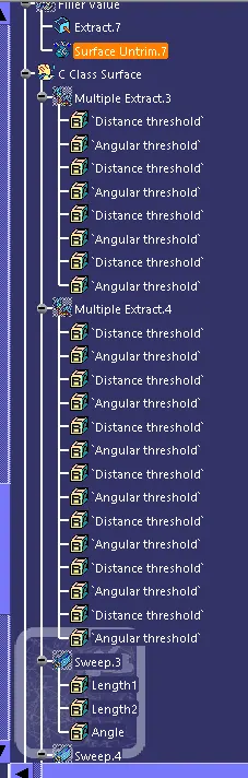
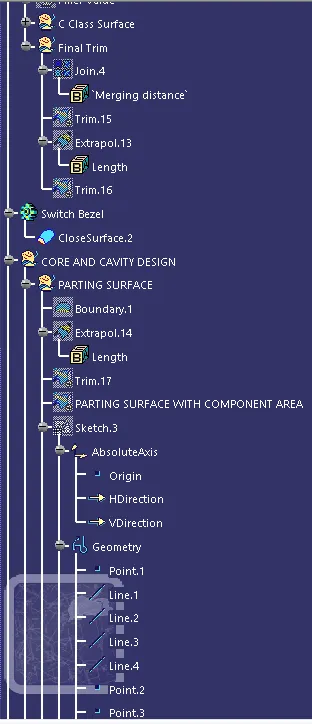
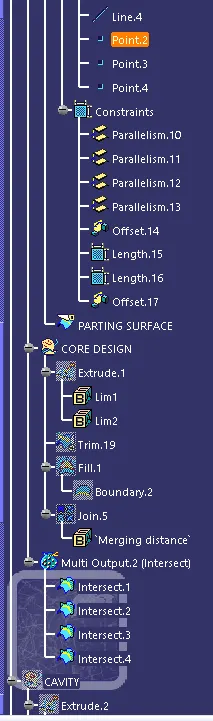
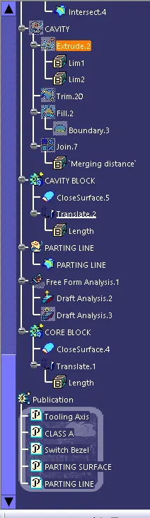
Tree Structure :
Views :
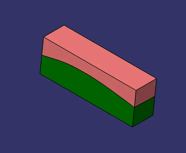
Isometric View
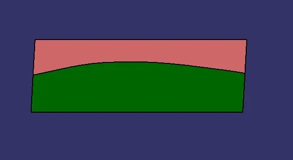
Front View
Side View
Top View