Photo Realistic Rendering
Assembly Of Chopper Model :
Aim : By Using Solidworks Software to Model the American Chopper.
Objective :
- To design individual parts of chopper with fully defined sketches and appropriate appearancres.
- To assemble all the individual parts of the chopper model by assigning suitable constraints.
- To render the chopper model by adding appearances, decals, lights, cameras, and background scenes.
Introduction :
Solid works: Solid works is a product of Dassault systems company. it is a software used to designing, assembling and real time rendering of the real time model. Any kind of complicated and sensitive designs can be easily modeled using the tools and interface of this software. The basic tools and its usage are explained in the description section.
Chopper model: Chopper is a customized bike which as powerful engine and simple parts with high precise shapes and edges. The basic parts in the chopper are chassis, engine, front wheel, front fender, rear wheel, real fender, oil tank, gas tank, front fork, chain part, pedal, transmission belt, and stand.
Design Methodology: ( FlowChart)
| Chopper Model |
| Part Modelling | Assembling of Parts | Scene Rendering |
|
|
|
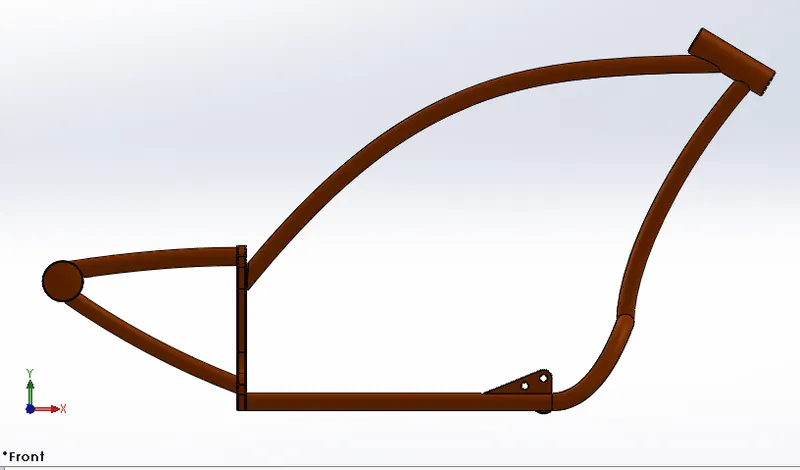
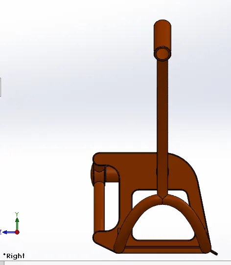
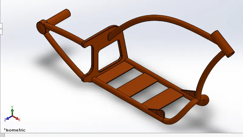
- Chassis:
Motorcycles have frame made of steel, aluminum or alloy. The frame consists mostly of hollow tubes and serves as a skeleton on which components like the gearbox and engine are mounted. The frame also keeps the wheels in line to maintain the handling of the motorcycles.
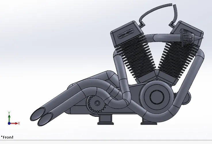
- Engine:
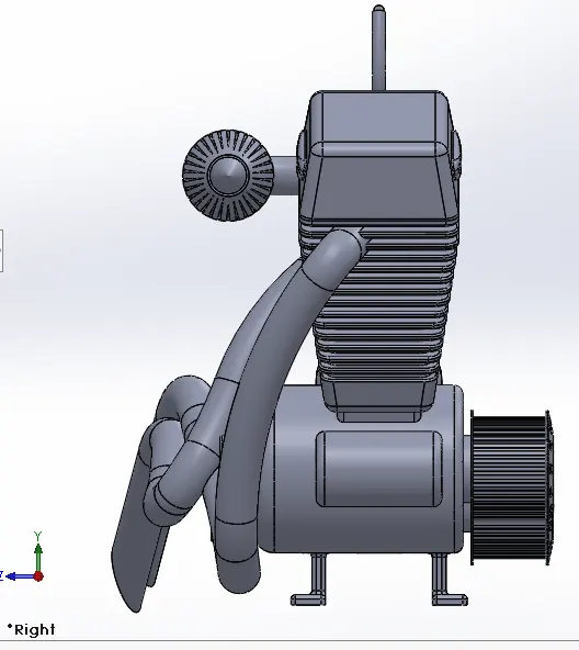
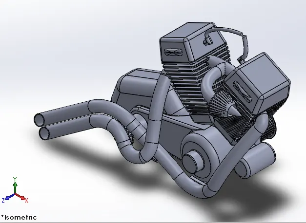
A Motorcycle engine is an engine that powers a motorcycle. Motorcycle engines are typically 2-stroke or 4-stroke internal combustion engine.
- Front Wheel and Rear Wheel:
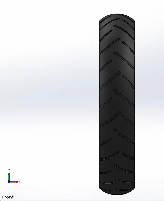
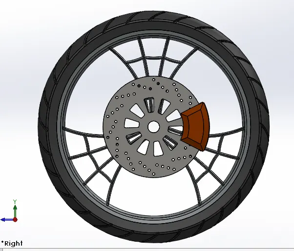
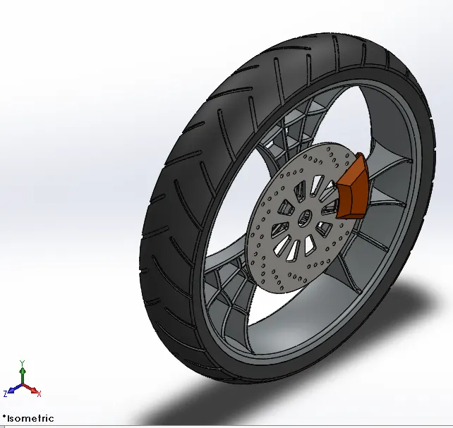
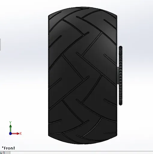
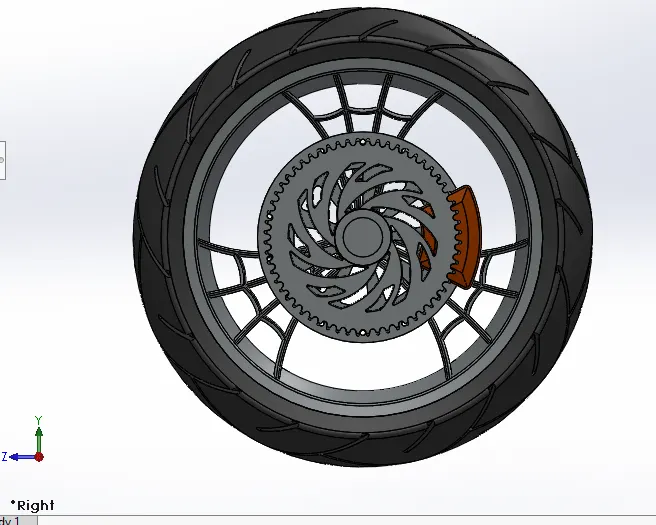
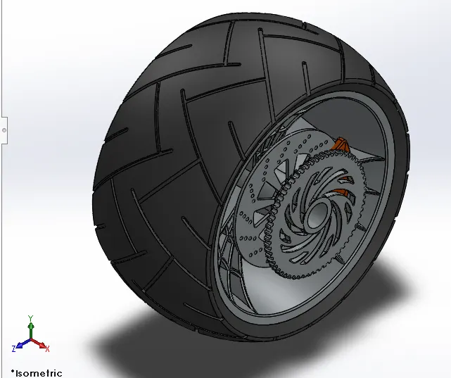
Motorcycle wheels are made tp cope with radial and axials forces. They also provide a way of mounting other critical components such as the brakes, final drive, and suspension. Wheels, and anything directly connected to them, are considered to be unsprung mass. The wheel consists of wheels rims, disc brake rotors, calipers, etc..,
- Front Fork:
A Motorcycle fork connects a motorcycle's front wheel and axle to its frame. Most forks incorporate the front suspension and front brake and allow the front wheel to rotate about the steering axis so that bike may be steered.
- Oil Tank and Gas Tank:
The oil tank is the part of the chopper. it consists of oil and supplies the oil to engine and other parts to smoothen the running of mating parts. A fuel tank ( or petrol tank ) is a safe container for flammable fluids. Though any storage tank for fuel may be so- called. The term is typically applied to the part of engine system in which the fuel is stored and propelled ( fuel pump ) or released (pressurized gas ) into an engine.
- Chain:
A bicycle chain is a roller chain that transfers power from engine to the drive wheel of a bike, thus propelling it.
- Pedal:
Pedal is the part of the chopper motorcycle attached to chassis, the driver can rest his foot on the pedal while driving.
- Transmission Belt:
A belt is a loop of flexible material used to link two or more rotating shafts machanically, most often parallel. Belt may be used as a source of motion, to transmit power efficiently or to track relative movement.
- KickStand:
A metal rod attached to a motorcycle, lying horizontally when not in use, may be kicked into a vertical position to support the vehicle when it is stationary.
Description:
Chassis:
Front View
Side View
Isometric View
Tools & Features Used:
Sketch picture : To insert Pictures for reference
Sketch : To create required sketches
Line : To draw circles
Spline : To draw the curves through interpolation of points
Intersection curve : To get an intersection curve obtained from projection of two curves
Boss-sweep : To obtain the solid body along the profile path
Boss-extrude : To obtain 3d solid from 2d sketch
Cut-Extruder : To subtract a solid position from a solid using 2d sketch
Reference Plane : To constructt a reference plane if existed references are not suitable or far away
Mirror : To mirror features or sketches along the selected reference
Split : To separate or split solid bodies
Combine : To combine or merge solid bodies
Dome : To create dome Surfaces on flat surfaces
Fillet : To convert sharp internal or external edges into smooth or round edges
Chamfer : To convert sharp edges into bevel edges
Smart dimensions : To add or edit dimensions of sketches
Engine:
Front View
Side View
Isometric View
Tools & Features Used :
Sketch Picture : To insert pictures for reference
Sketch : To create required sketches
Line : To drawing lines & construction lines
Circle : To drew circle
Arc : to drew arc
Spline : To drew curves through interpolation of points
Convert Entities : to convert edges or curves into lines
Intersection Curve : To get intersection curve obtained from projection of two curves
Boss-Extrude : To obtain the solid body along the profile path
Boss-Extrude : To obtain 3d solid from 2d sketch
Boss-Revolve : To revolve 2d sketch along the reference to obtain solid body
Reference Plane : To construct a reference plane if existed references are not suitable or far away
Mirror : To mirror features or sketches along the selected reference
Split : To separate or split solid bodies
Combine : To combine or merge solid bodies
Dome : To create dome surfaces on flat surfaces
Fillet : To convert sharp internal or external edges into smooth or round edges
Chamfer : to convert sharp edges into bevel edges
Circular Pattern : To create a pattern of feature or body along a circular reference
Linear Pattern : To create a pattern of feature or body along a linear reference
Composite Curve : To obtined combined composite curve from two or more curves
Smart dimensions : To add or edit dimensions of sketches
Front Wheel :
Front View
Side View
Isometric View
Tools & Features Used :
Sketch : To create required sketches
Line : To drawing lines and construction lines
Circles : To draw arc
Spline : To draw curves through interpolation of points
Convert Entities : To convert edges or curves into lines
Offset Entities : To offset edges or lines to duplicate the edges
Boss-Extrude : To obtain 3d solid from 2d sketch
Boss-Revolve : To revolve 2d sketch along the reference to obtain solid body
Cut- Extrude : To subtract a solid portion from a solid using 2d sketch extrusion
Cut-Revolver : To subtract a solid portion from a solid using 2d sketch revolve
Combine : To combine or merge solid bodies
Fillet : To convert sharp internal or external edges into smooth or round edges
Chamfer : to convert sharp edges into bevel edges
Circular Pattern : To create a pattern of feature or body along a circular reference
Linear Pattern : To create a pattern of feature or body along a linear reference
Smart dimensions : To add or edit dimensions of sketches
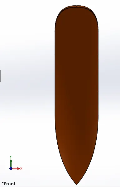
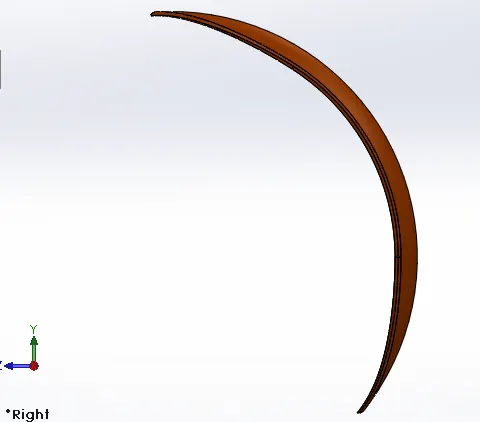
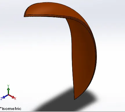
Front Fender:
Front View
Side View
Isometric View
Tools & Features Used :
Sketch : To create required sketches
Line : To drawing lines and construction lines
Spline : To draw curves through interpolation of points
Split : To separate or split solid bodies
Fillet : To convert sharp internal or external edges into smooth or round edges
Boss-Revolve : To revolve 2d sketch along the reference to obtain solid body
Smart dimensions : To add or edit dimensions of sketches
Rear wheel :
Front View
Side View
Isometric View
Tools & Features Used :
Sketch : To create required sketches
Line : To drawing lines and construction lines
Convert Entities : To convert edges or curves into lines
Offset Entities : To offset edges or lines to duplicate the edges
Boss-Extrude : To obtain 3d solid from 2d sketch
Boss-Revolve : To revolve 2d sketch along the reference to obtain solid body
Cut- Extrude : To subtract a solid portion from a solid using 2d sketch extrusion
Cut-Revolver : To subtract a solid portion from a solid using 2d sketch revolve
Combine : To combine or merge solid bodies
Fillet : To convert sharp internal or external edges into smooth or round edges
Chamfer : to convert sharp edges into bevel edges
Circular Pattern : To create a pattern of feature or body along a circular reference
Linear Pattern : To create a pattern of feature or body along a linear reference
Smart dimensions : To add or edit dimensions of sketches
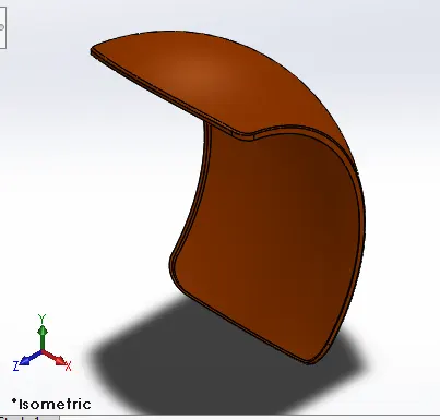
Rear Fender :
Front View
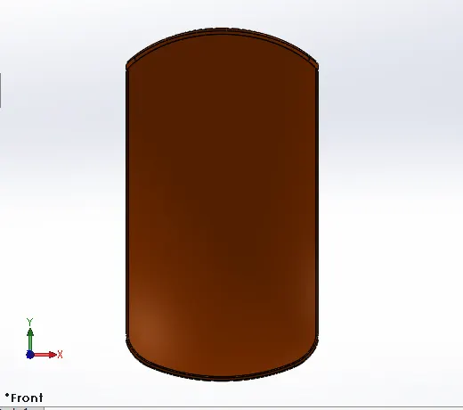
Side View
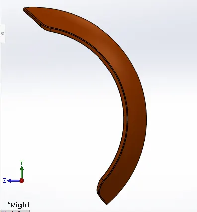
Isometric View
Tools & Features Used :
Sketch : To create required sketches
Line : To drawing lines and construction lines
Spline : To draw curves through interpolation of points
Split : To separate or split solid bodies
Fillet : To convert sharp internal or external edges into smooth or round edges
Boss-Revolve : To revolve 2d sketch along the reference to obtain solid body
Smart dimensions : To add or edit dimensions of sketches
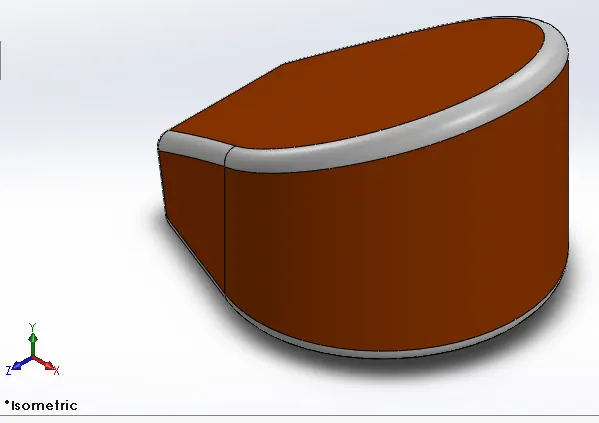
Oil Tank:
Front View
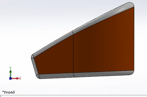
Side View
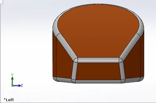
Isometric View
Tools & Features Used :
Sketch : To create required sketches
Line : To drawing lines and construction lines
Spline : To draw curves through interpolation of points
Split : To separate or split solid bodies
Fillet : To convert sharp internal or external edges into smooth or round edges
Boss-Extrude : To obtain 3d solid from 2d sketch
Combine : To combine or merge solid bodies
Shell : To convert solid bodies into shells
Smart dimensions : To add or edit dimensions of sketches
Gas Tank:
Front View
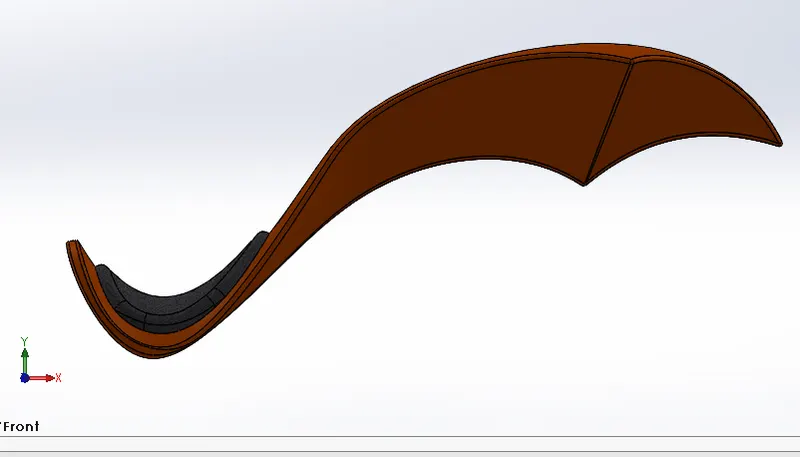
Side View
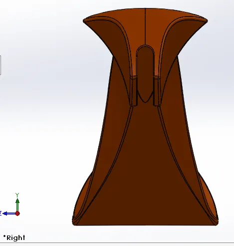
Isometric View
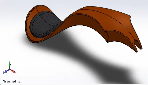
Tools & Features Used :
Sketch Picture : To insert pictures for reference
Sketch : To create required sketches
Line : To drawing lines & construction lines
Spline : To draw curves through interpolation of points
Split : To separate or split solid bodies
Fillet : To convert sharp internal or external edges into smooth or round edges
Boss-Extrude : To obtain 3d solid from 2d sketch
Reference Plane : To construct a reference plane if existed reference are not suitable or far away
Surface-loft : To create surface along the profiles
Surface-Knit : To Combine adjacent non intersecting features
Surface-Sweep : To sweep along the sketch to obtain surface
Boundary-Surface : To create surface from closed profile
Cut-sweep : To cut the surface along the profile through sweep along the reference
Shell : To convert solid bodies into shells
Mirror : to mirror features or sketches along the selected reference
Smart dimensions : To add or edit dimensions of sketches
Front Fork :
Front View
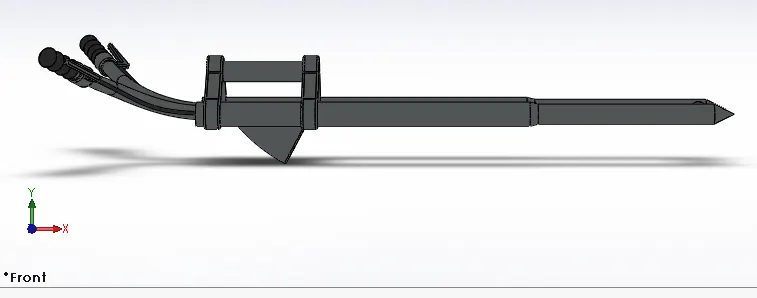
Side View
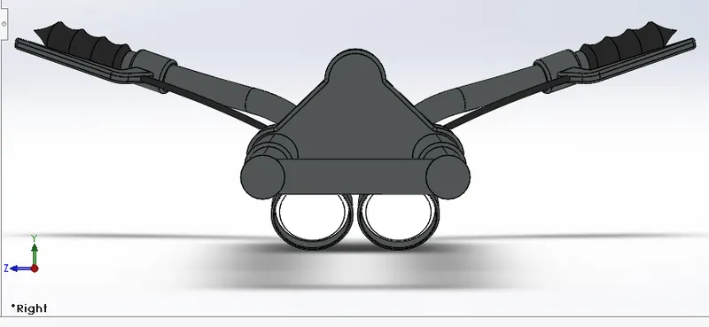
Isometric View
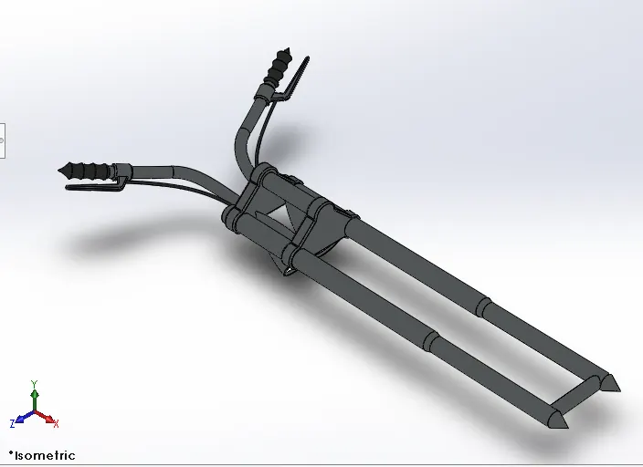
Tools & Features Used :
Sketch : To create required sketches
Line : To drawing lines and construction lines
Circle : To draw arc
Spline : To draw curves through interpolation of points
Convert Entities : To convert edges or curves into lines
Intersection Curve : To get an intersection curve obtained from projection of two curves
Boss-sweep : To obtain the solid body along the profile path
Boss-Extrude : To obtain 3d solid from 2d sketch
Boss-Revolve : To revolve 2d sketch along the reference to obtain solid body
Cut- Extrude : To subtract a solid portion from a solid using 2d sketch extrusion
Reference Plane : To construct a reference plane if existed reference are not suitable or far away
Mirror : To mirror features or sketches along the selected reference
Combine : To combine or merge solid bodies
Dome : To create dome Surfaces on flat surfaces
Fillet : To convert sharp internal or external edges into smooth or round edges
Linear Pattern : To create a pattern of feature or body along a linear reference
Smart dimensions : To add or edit dimensions of sketches
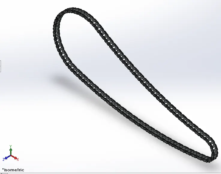
Chain :
Front View
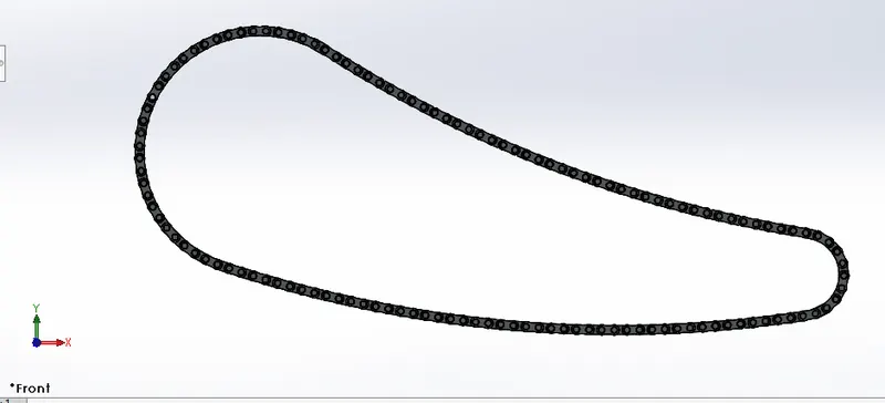
Side View
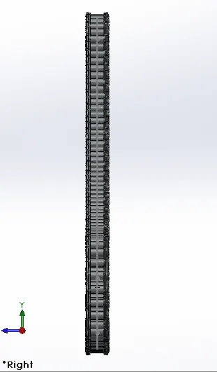
Isometric View
Tools & Features Used :
Sketch : To create required sketches
Line : To drawing lines and construction lines
Circle : To draw circle
Arc : To draw arc
Spline : To draw curves through interpolation of points
Block : ro create separate and save sketch from the existing sketch
Boss-Extrude : To obtain 3d solid from 2d sketch
Mirror : To mirror features or sketches along the selected reference
Combine : To combine or merge solid bodies
Fillet : To convert sharp internal or external edges into smooth or round edges
Curve Pattern : To create a pattern of feature or body along a Curved reference
Smart dimensions : To add or edit dimensions of sketches
Pedal :
Front View
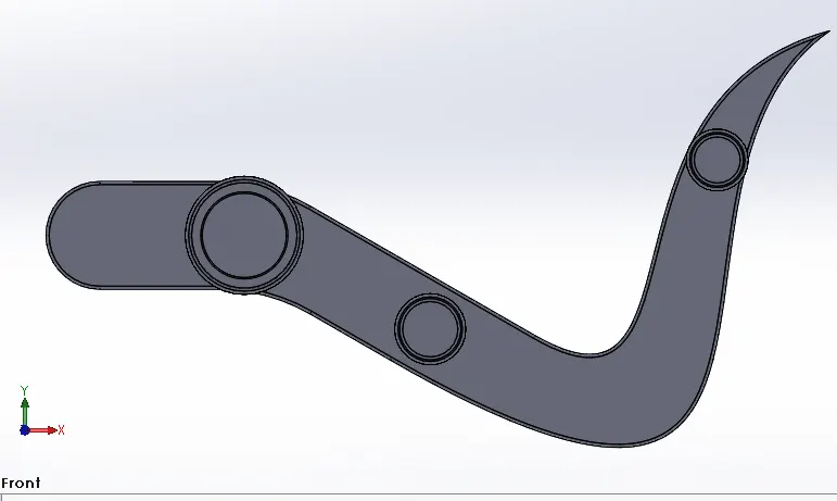
Side View
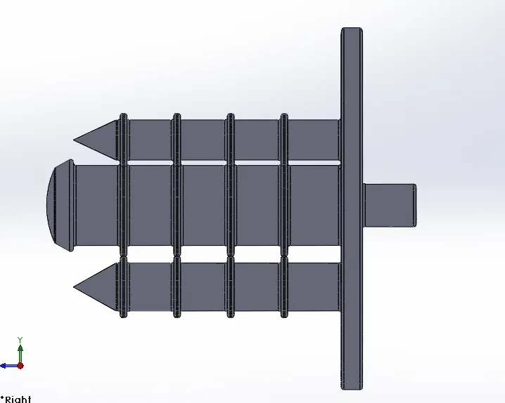
Isometric View
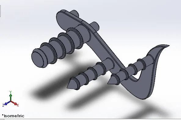
Tools & Features Used :
Sketch : To create required sketches
Line : To drawing lines and construction lines
Circle : To draw circle
Arc : To draw arc
Spline : To draw curves through interpolation of points
Block : ro create separate and save sketch from the existing sketch
Boss-Extrude : To obtain 3d solid from 2d sketch
Boss-Revolve : To revolve 2d sketch along the reference to obtain solid body
Combine : To combine or merge solid bodies
Dome : To create dome Surfaces on flat surfaces
Fillet : To convert sharp internal or external edges into smooth or round edges
Chamfer : to convert sharp edges into bevel edges
Linear Pattern : To create a pattern of feature or body along a linear reference
Smart dimensions : To add or edit dimensions of sketches
Transmission Belt :
Front View
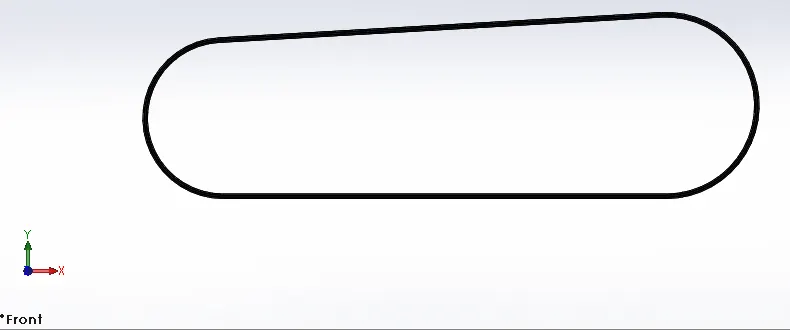
Side View
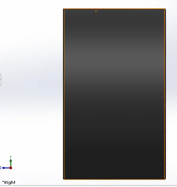
Isometric View
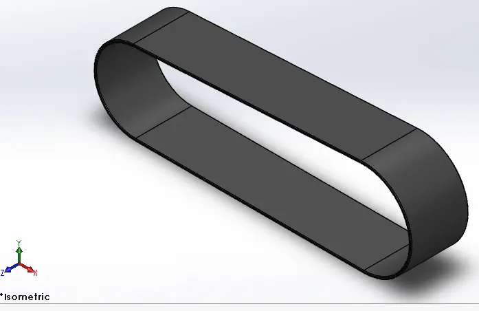
Tools & Features Used :
Sketch : To create required sketches
Line : To drawing lines and construction lines
Arc : To draw arc
Boss-Extrude : To obtain 3d solid from 2d sketch
Fillet : To convert sharp internal or external edges into smooth or round edges
Smart dimensions : To add or edit dimensions of sketches
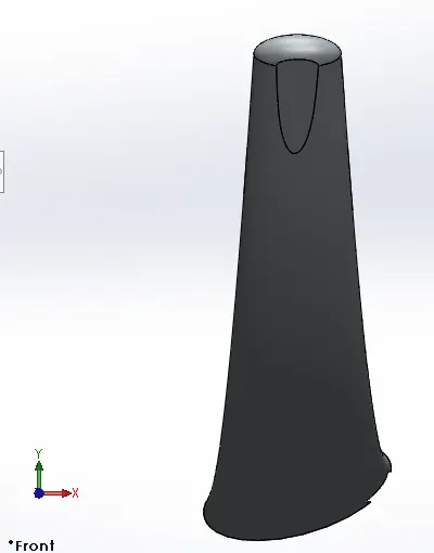
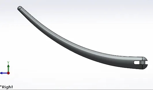
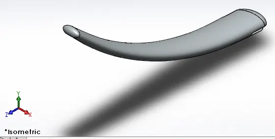
Kick Stand :
Front View
Side View
Isometric View
Tools & Features Used :
Sketch : To create required sketches
Line : To drawing lines and construction lines
Arc : To draw arc
Boss-Extrude : To obtain 3d solid from 2d sketch
Dome : To create dome Surfaces on flat surfaces
Cut- Extrude : To subtract a solid portion from a solid using 2d sketch
Loft : To create surface along the profiles
Split : To separate or split solid bodies
Fillet : To convert sharp internal or external edges into smooth or round edges
Smart dimensions : To add or edit dimensions of sketches
Assembly :
Front View
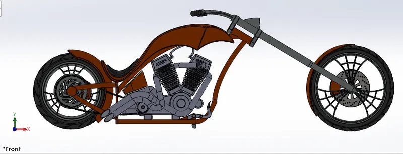
Side View
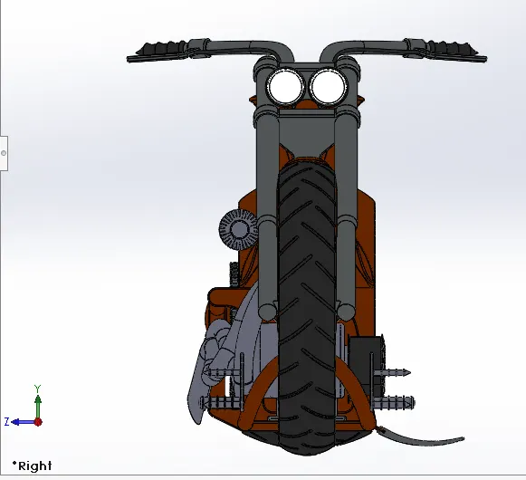
Isometric View
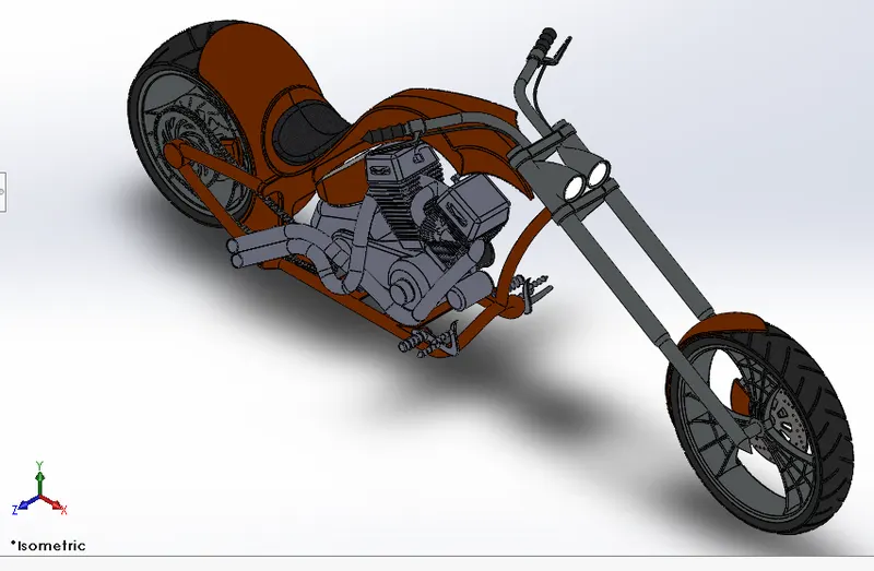
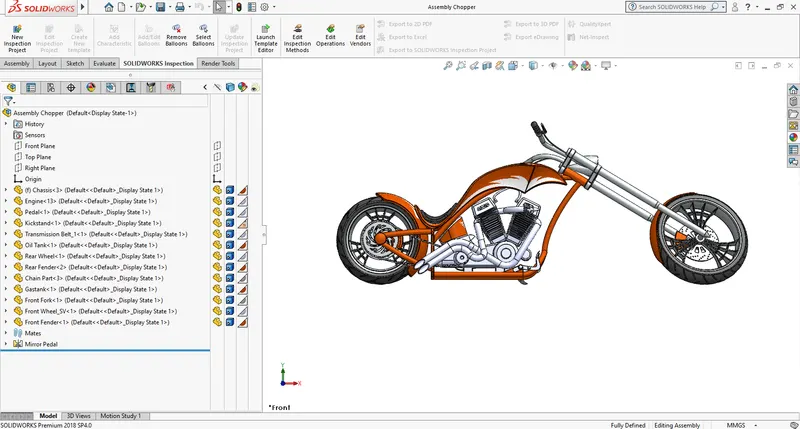
Tools & Features Used :
Mates : To create constraints between surfaces
Rendering :
Front View
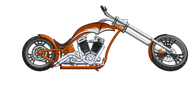
Side View
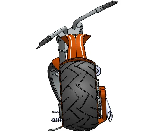
Top View
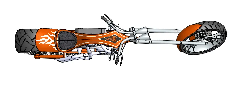
Isometric View
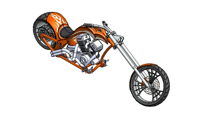
Camera View
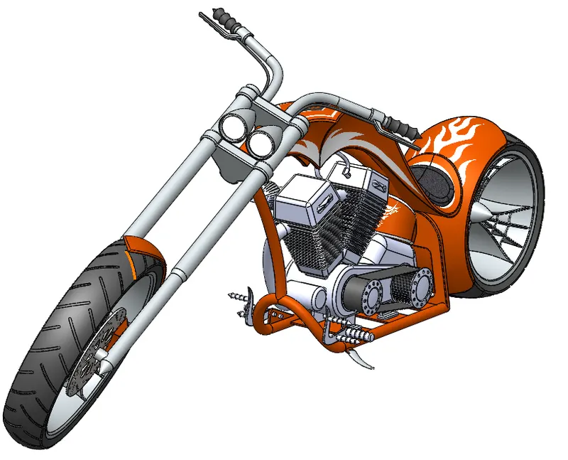
Rendering with Environment
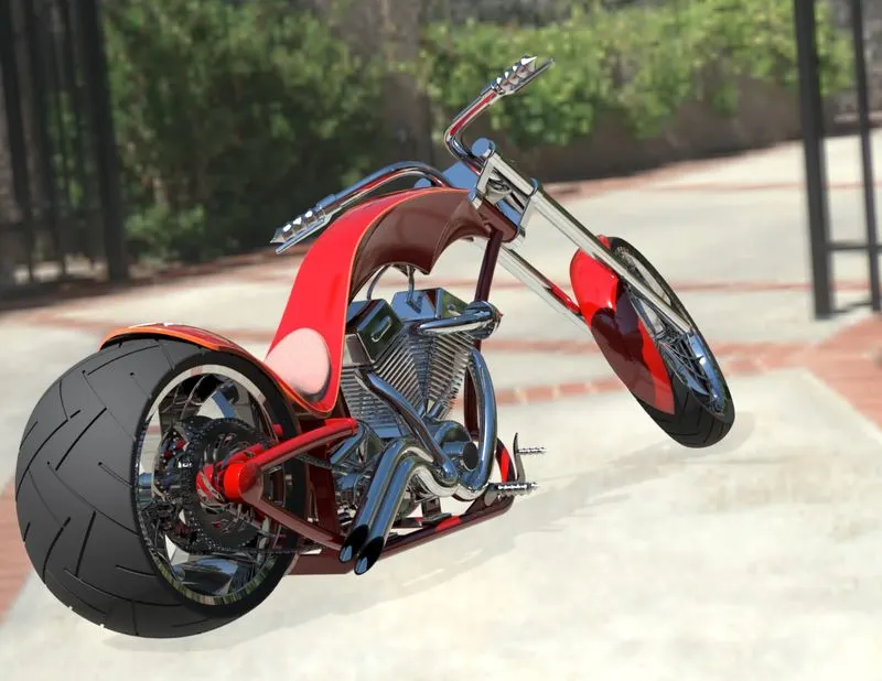
Tools & Features Used :
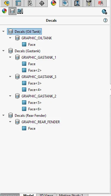
Decals : Graphics or designs used on chopper bodies
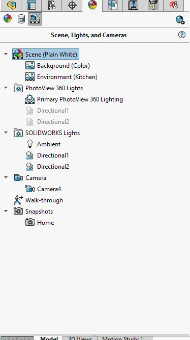
Lights and Cemera : To adjust lighting and camera angles
Render Preview : To preview the final render before rendering
Render : To render in required quality and sizes
Conclusion :
Thus the Chopper model is modelled, assembled and rendered using solid works software.
Link for part files, assembly files and rendering files : Shakthivel_Assembly_Chopper
American Chopper Rendering
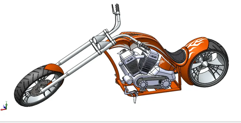
- Rendering model link shown in blow
Rendering Views
- Front View
- Side View
- Top View
- Isometric View
- Camera Setup View