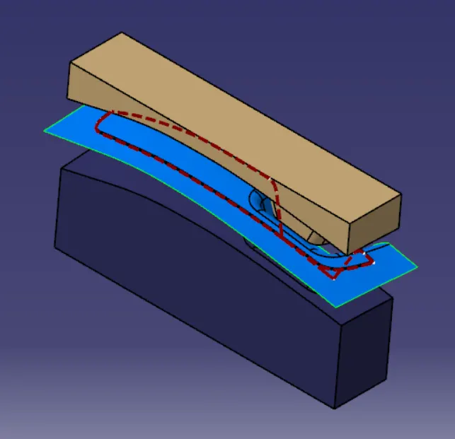
Week 8 - Challenge 5 - Core & Cavity Design
Core and Cavity Design
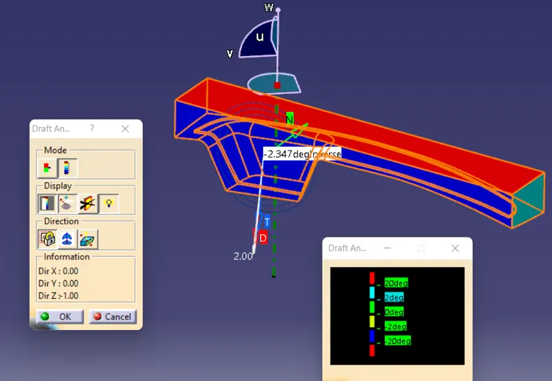
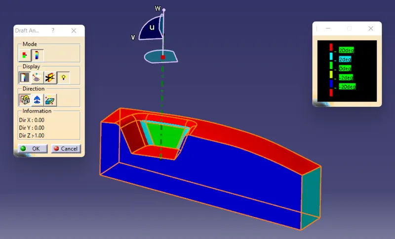
Switch Bezel Draft Analysis: Draft Analysis is done to check whether the part created can be removed easily from the cavity easily. It is done by giving different color zones which shows any deviation from the specified draft angle and direction.
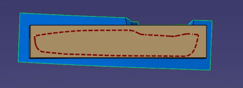
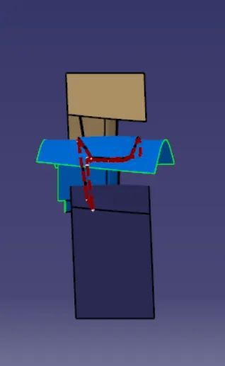
Tooling axis: It is created to specify the direction through which core has to pass into the cavity region. It plays a vital role in determining the direction of core as it should not affect the final product after cooling when it is removed. It should be in such a way to prevent side cores so that the cost will reduce.
Steps for specifying tooling axis:
- Use Join command and confirm that surfaces are joined together properly with no gaps.
- Analyse the surface model and decide the best tooling direction.
- Extract the base surface using Multi Body extract.
- Create a point at the center, and create axis system at that point.
- Select the YZ plane and enter the sketch mode.
- Intersect surface and YZ plane, get the boundary line at the intersection.
- Create the two lines from the angled line on the either sides.
- Create a bisecting line from those two lines.
- Now select XZ plane and draw the cross section of the class surface.
- Draw the line along the intersection boundary.
- Create line from the point and give angle of 3degree with the previous line.
- Keep the line passing through the center point..
- Create the bisecting line from the obtained two bisecting axis lines.
- Now name it as a Tooling axis which is required axis for the tool passing.
Draft Analysis of Plastic Component:
Core Component
Cavity Component
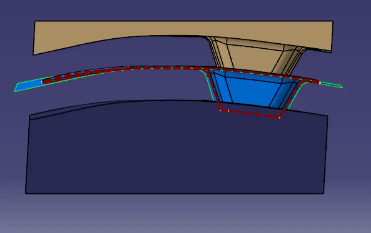
Core and Cavity Views:
Front View
Top View
Side View
Iso View