Photo Realistic Rendering
AMERICAN CHOPPER
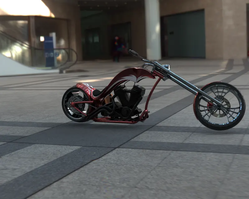
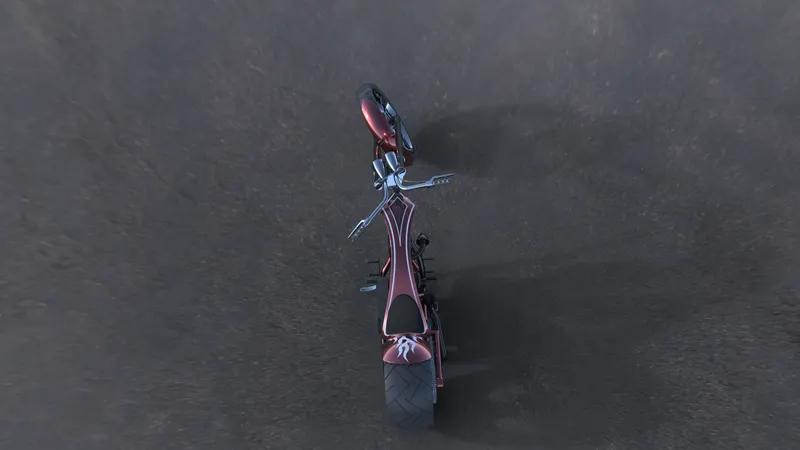
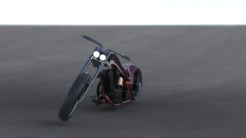
Aim : To make an assembly of American Chopper
Objective : Model the parts required for assembly. Adding appearance, colour, decals and scenes. Rendering using
360 Photorealistic Views and Solidworks Visualise.
Software Used : Solidworks and Solidworks Visualise.
Introduction :
PART MODELLING : Part modelling means to create replica of the parts in a virtual manner required for assembly. Parts are modelled seperately and then used for the assembly.
Tools/Features Description:
Sketch : This is used to draw the model in 2D with respect to plane/view/face. It consists of suboptions Sketch and 3D skecth which can be used suitably. It has various options like line, circle,, rectangle, offset, convert,etc.
Convert Entities : To project previous sketch on the required plane which acts as a reference for current sketching.
Offset Entities : Offset the Sketch to the required dimension which prevents drawing the sketch again.
Extrude Boss/Base : It is used to convert 2D sketch into 3D model.
Extrude Cut : Used to remove material from 3D model which is contradiction to Boss Extrude.
Lofted Base : Used to add materials between 2 or more profiles which should be closed and spaced.
Revolved Base : Used to create 3D model around the axis or referance line.
Linear Pattern : Used to replicate one or more features along the one or two linear paths.
Circular Pattern : Used to replicate the features along the axis.
Fillet : Used to create rounded internal/external profile on an edge.
Chamfer : Used to remove the material at the edges of 3D model.
Shell : Used to remove inner portion of the model leaving required wall thickness thereby making a hollow model.
Reference plane : Used to create new plane required for sketching.
Spline : Used to create complex curves by controlling spline points and handles.
Combine : Allows to combine multiple bodies into single solid body.
Split : Used to project an entity onto other surfaces. We can split the faces on multiple bodies using this alone.
Dome : Used to create dome on 3D model or shapes.
Swept Boss : Used to sweep profile in a required path/direction/sketch
Cut Sweep : Used to remove material from the model by sweeping closed profile along closed/open path.
SURFACE MODELLING : Create surface of any dimension more precisely. It plays an important role in Automotive and Aeronautical design field.
Surface Features Description :
Extrude surface : Used to convert 2D skecth into 3D surface.
Ruled Surface : Used to create surface from the selected edge in a specified manner.
Trim Surface : To remove connected surface in a suitable shape or direction.
Knit Surface : To combine two or more faces/surfaces together. We can use merge entities to make them as a single entity and control the gap between them.
Surface Sweep : Used to create surface by moving profile along the path.
Surface Loft : Creates complex shaped surface by making transition between multiple profiles and guide curves.
DESCRIPTION OF THE PARTS MODELLED AND TO MAKE AND AMERICAN CHOPPER
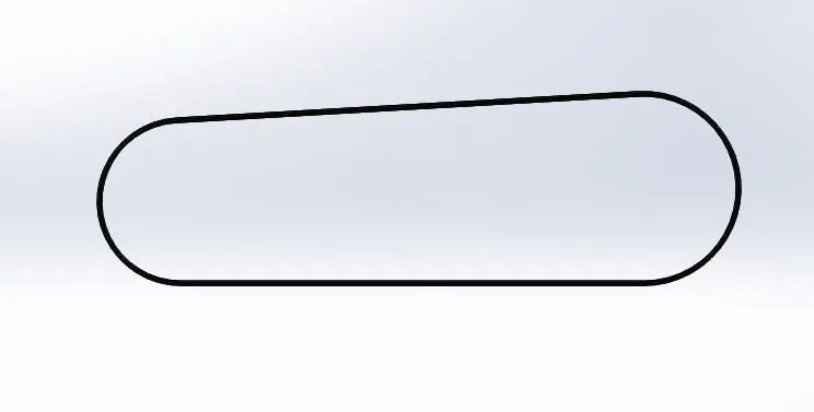
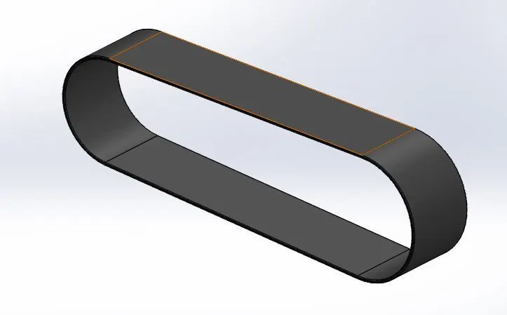
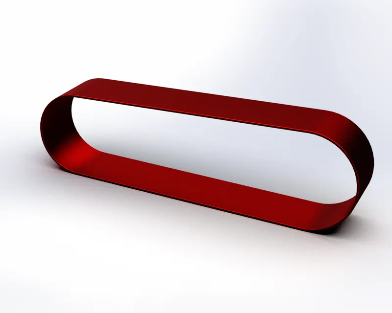
1) Transmission Belt : It is a closed loop made of flexible material used to connect two or more shafts parallely. They are used to transfer power more efficiently.
Features used :
- Extrude Boss
- Fillet Rendered Image
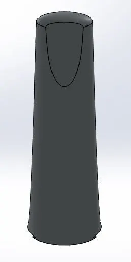
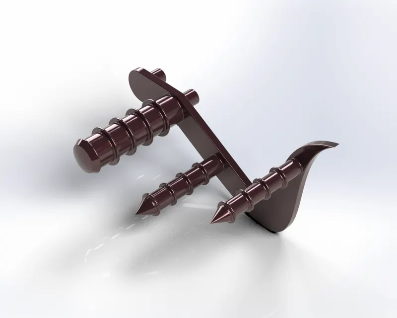
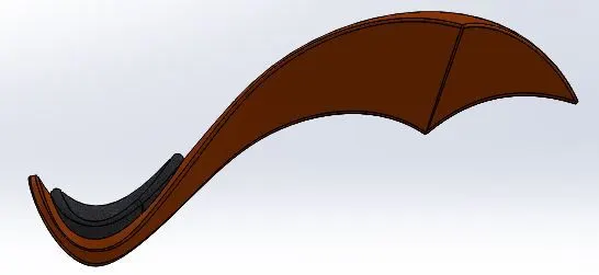
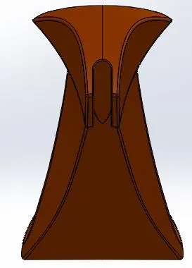
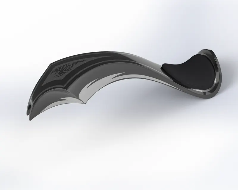
2) Kick Stand : It is used to keep two wheeler upright without leaning against any other object. It is flipped from the chassis and make contact with ground as a support.
Features Used :
- Spline
- Loft
- Extrude Cut
- Dome
- Boss Extrude Rendered Image
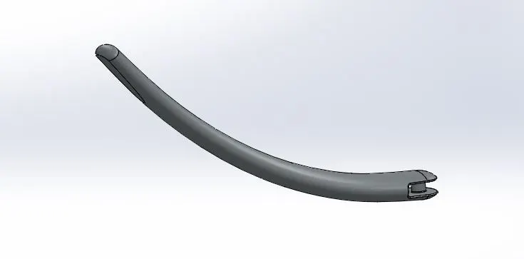
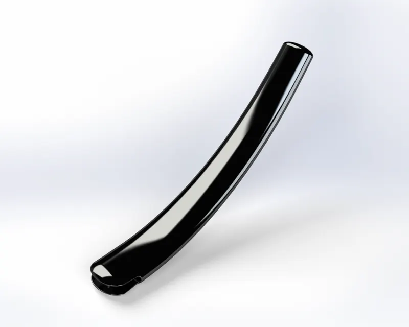
3) Front Fender : It is an American English term for an automobile part that frames the wheel. It prevents the rock, liquid or mud being thrown into air towards other vehicles or pedestrians by the rotating tyre.
Features used :
- Revolved Boss
- Split
- Fillet Rendered Image
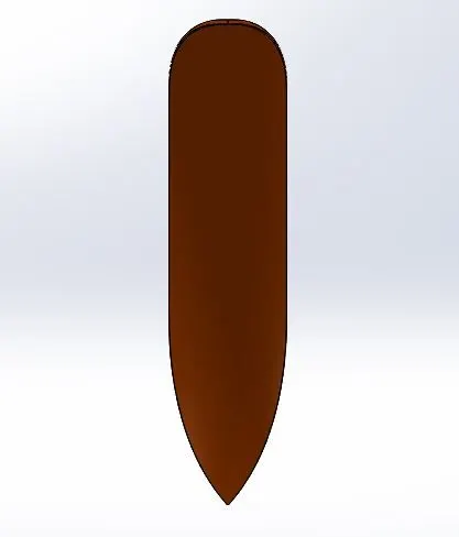
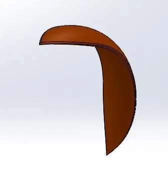
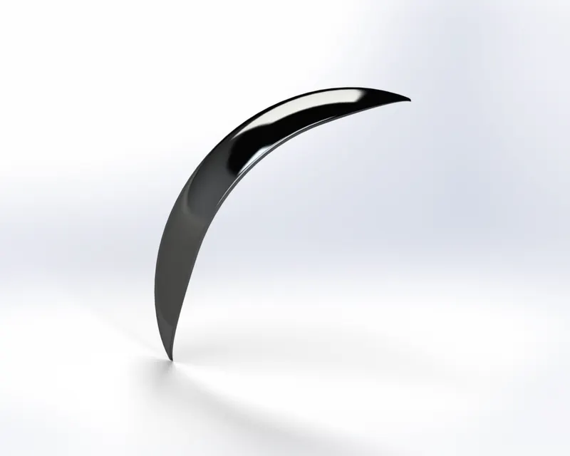
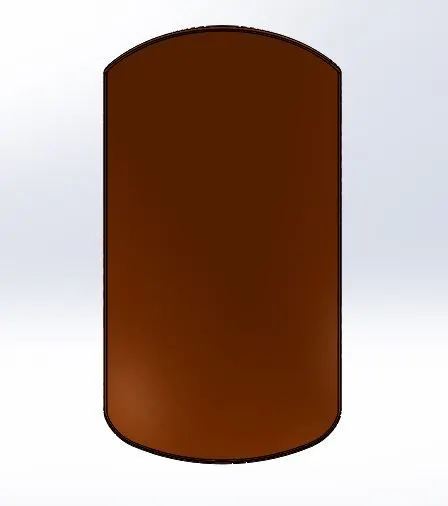
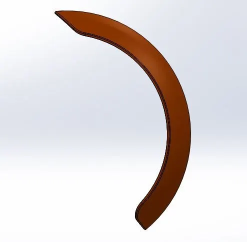
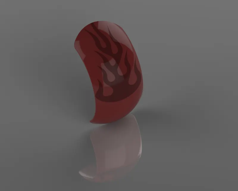
4) Rear Fender : It is an American English term for an automobile part that frames the wheel. It prevents the rock, liquid or mud being thrown into air towards other vehicles or pedestrians by the rotating tyre.
Features Used :
- Revolved Base
- Split
- Fillet
- Shell Rendered Image
5) Chain : It is used to transmit power from engine to rear wheel. They are usually made of carbon or alloy steel.
Features used :
- Boss Extrude
- Fillet
- Curve Pattern
- Mirror Rendered Image
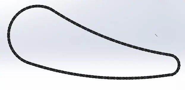
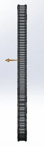
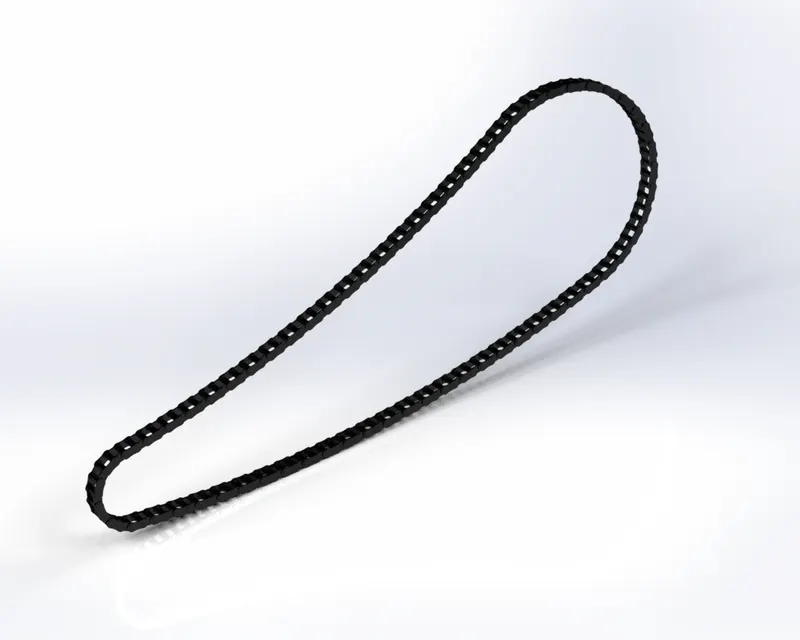
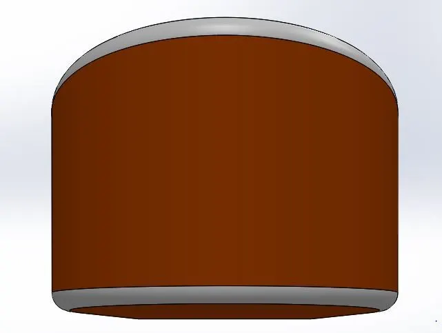
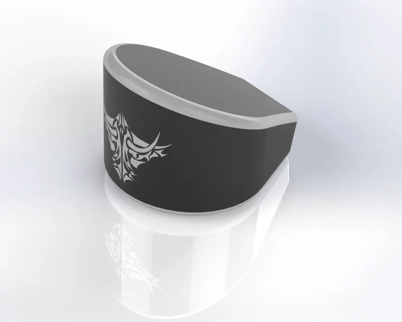
6) Oil Tank : This acts as a storage container of lubricating oil required for combustion engines.
Features Used :
- Boss Extrude
- Combine
- Shell Rendered Image
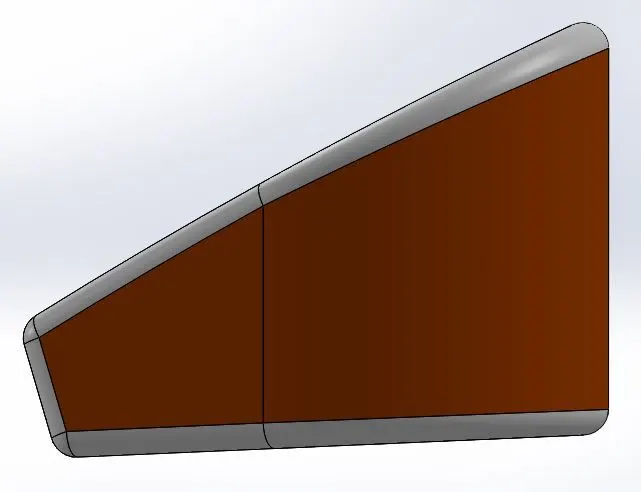
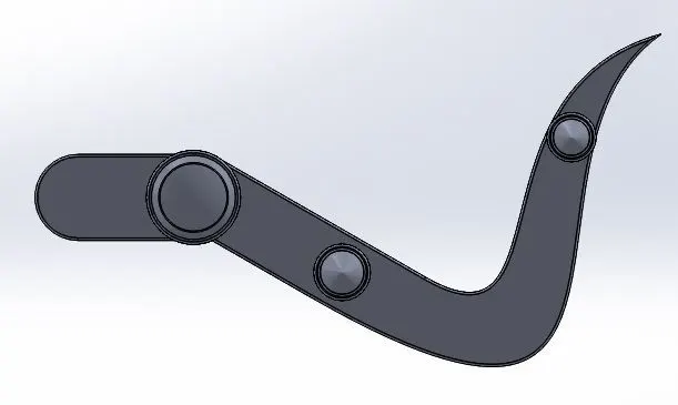
7) Pedal : Its function is to shift the gear required for suitable speed and also to apply brake.
Features used :
- Boss Extrude
- Chamfer
- Fillet
- Linear Pattern
- Dome Rendered Image
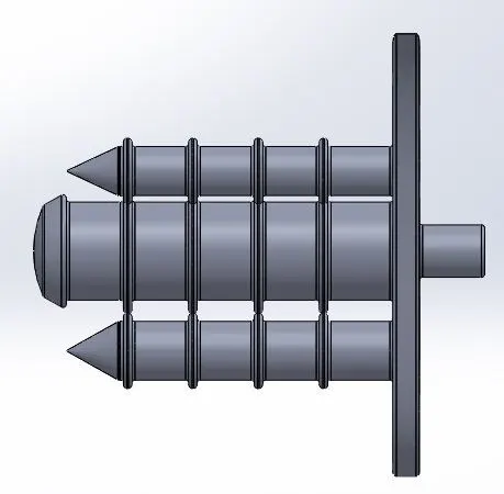
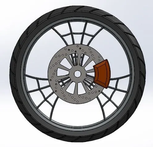
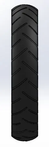
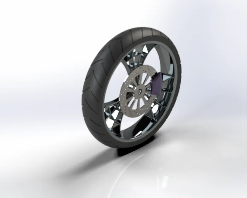
8) Front Wheel : It is a circular part attached with tyre and center is connected to bearing about which wheel rotates and enable movement of vehicle.
Features Used :
- Extrude Cut
- Boss Extrude
- Fillet
- Revolve
- Circular pattern
- Combine Rendered Image
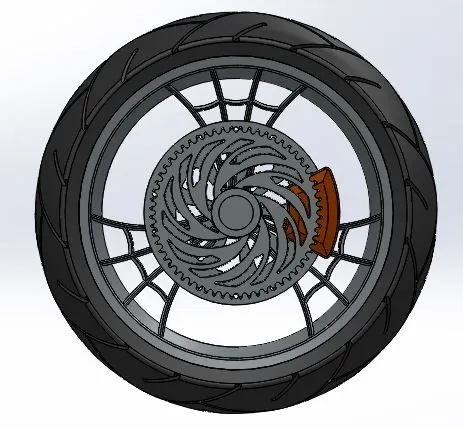
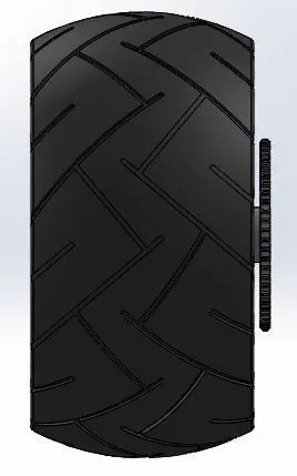
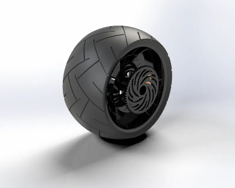
9) Rear Wheel : It is a circular part where tyre is mounted and center is connected to bearing and chain which
makes vehicle to move.
Features used :
- Circular pattern
- Cut extrude
- Fillet
- Revolve
- Boss Extrude
- Combine Rendered Image
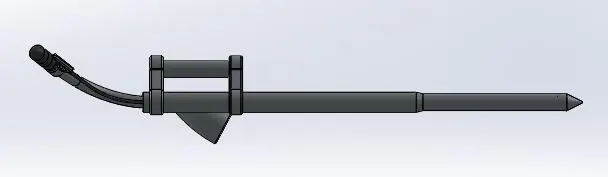
10) Front Fork : Fork connects front wheel and axle to its frame and using this can control the direction at which vehicle wants to move. Head light is mounted to this.
Features Used :
- Dome
- Extrude Boss
- Revolve
- Fillet
- Combine
- Linear Pattern
- Revolve Cut
- Sweep
- Mirror Rendered Image
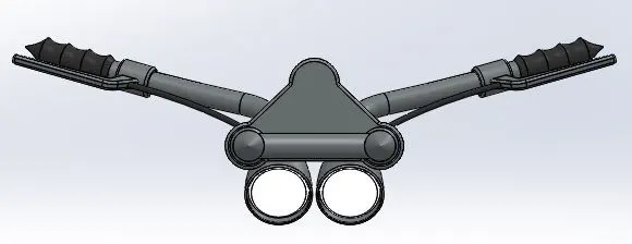
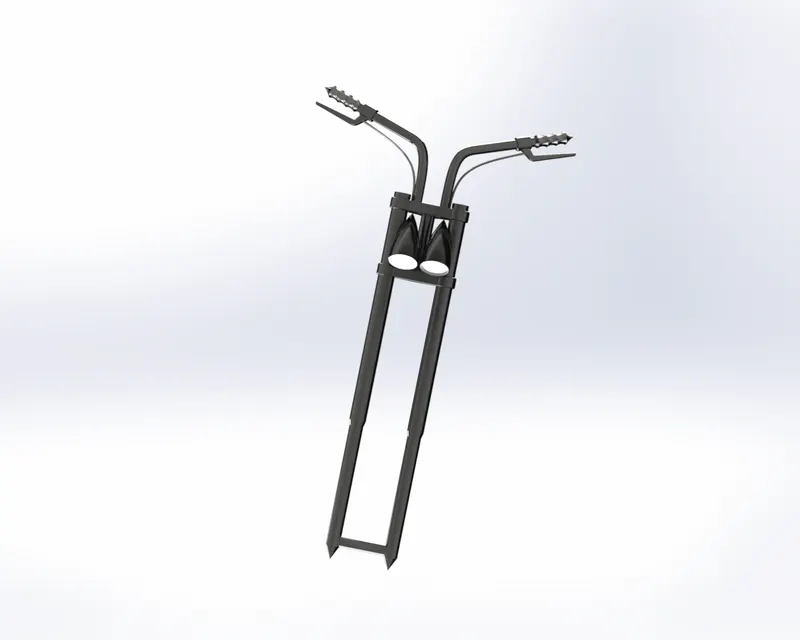
11) Chassis : It functions as a skeleton of vehicle that holds the engine, gear box, pedal, kick stand and front fork.
Features Used :
- Extrude Cut
- Combine
- Mirror
- Boss Extrude
- Chamfer
- Fillet
- Sweep
- Dome
- Revolve
- Split
- Project Curve Rendered Image
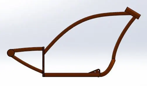
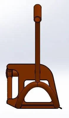
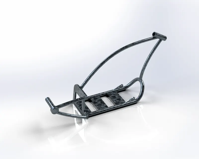
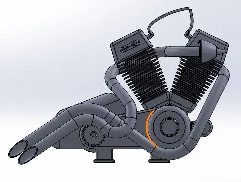
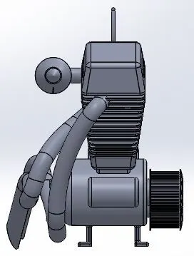
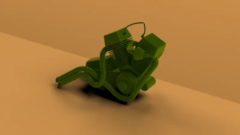
12) Engine : A machine that converts one form of energy to mechanical energy.In IC engines heat produced by combusted gases will produce piston to reciprocate.
Features used :
- Sweep
- Fillet
- Split
- Boss extrude
- Revolve
- Circular Pattern
- Chamfer
- Dome
- Linear Pattern Rendered Image
13) Gas Tank : It is storage container of flammable fuel. Fuel is sent to the engines for combustion to happen and make mechanical movement.
Features Used :
- Surface Sweep
- Surface Trim
- Surface Loft
- Mirror
- Surface Knit
- Fillet
- Cut Sweep
- Shell Rendered Image
ASSEMBLY OF AMERICAN CHOPPER
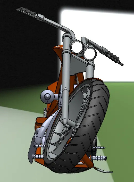
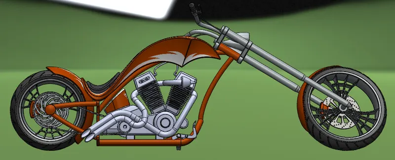
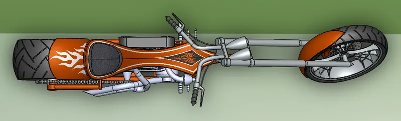
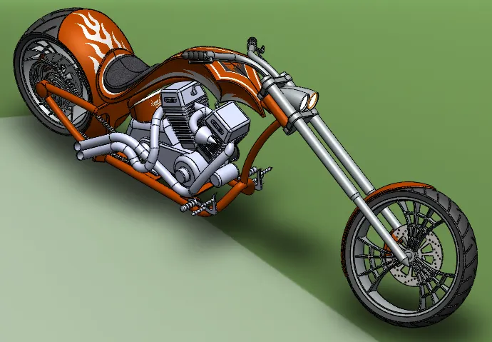
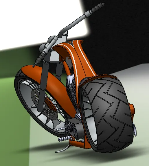
Parts Modelled are inserted into assembly area one by one by using insert component option and mating with constrianed condition.
Insert Component : Used to add parts into assembly area.
Mate : It is a geometrical relations between the parts to be assembled. It consists of different types like parallel, perpendicular, coincident, distance, angle, concentric.
Move Component : Used to move the components within its degrees of freedom.
Rotate Component : To rotate the components within its degrees of freedom.
RENDERING :
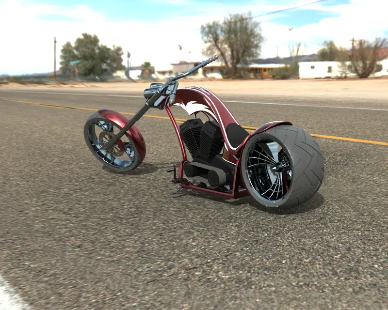
It is the process of generating photorealistic or non-photorealistic image from a 2D/3D model by means of computer program. In Solidworks rendering can be done by two ways, Photoview 360 and Solidworks Visualise.
Photoview 360 : It is a visualisation and render tool included in Solidworks software. It provides high interactive environment for viewing designs and also to create photorealistic renderings.
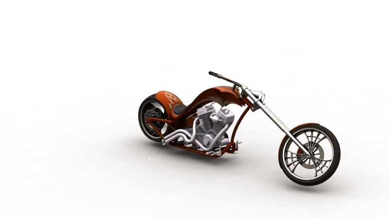
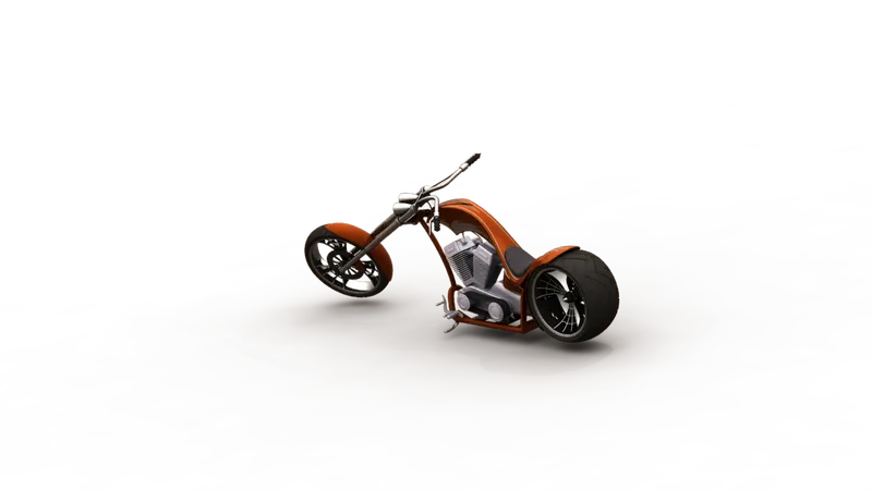
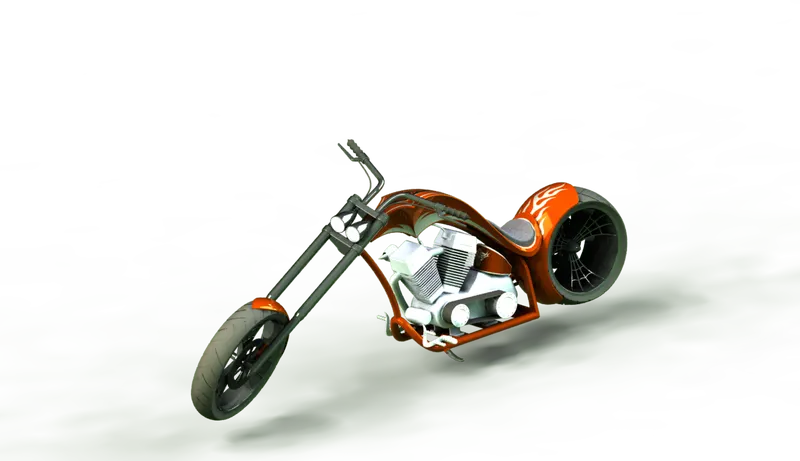
Visualise : It is a software part of solidworks platform which allows users to create magazine quality images. It consists of scenes, appearances, HD environment, backplates that can be added to make an object look realistic.
CONCLUSION :
- Parts of the Chopper modelled using Solidworks.
- Modelled Parts are assembled together to form American Chopper.
- Rendering of the Assembly made using Photo-view 360 and Visualise.