Week 8 - Challenge 5 - Core & Cavity Design
AIM: To create the core and cavity for the switch bezel considering all the rules.
Tooling axis:
It is the axis in which the direction core and cavity open. This is the very important for production of plastic component.
There area so many methods for creation of cooling axis. Intersection is the one of the methods for creating the tooling axis.
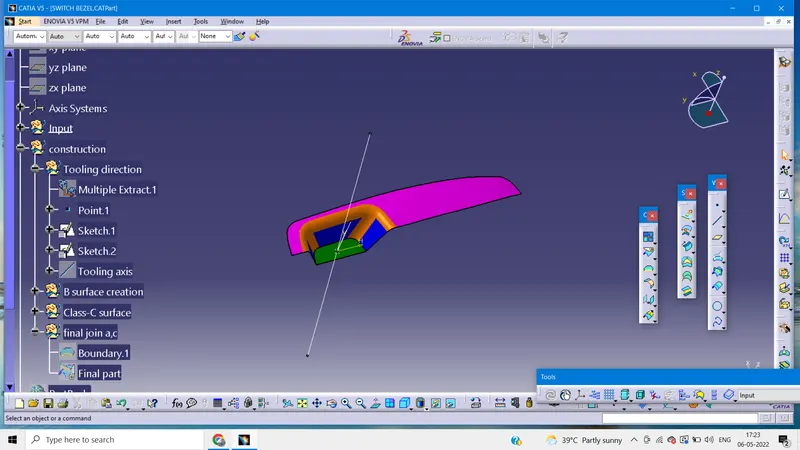
Bisection method:
For doing this you should find out, what is best tooling direction. Rotate the part and see all the directions and choose the which direction will be comfortable.
Then create the point on the base, mostly create the poin where hole or pocket are given. After that insert tooling axis in the point. Create the mean line,then bisect all these lines to get the main tooling axis. THis cooling axis can be cleared all the faces of the part.
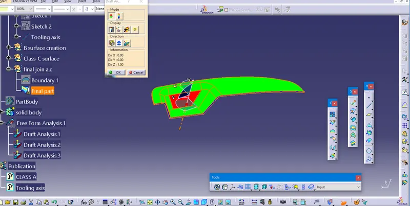
DRAFT ANALYSIS:
1.Go to insert>analysis>feature draft analysis.
2.Align the tooling axis with compass.
3.Click on the surface and see that surface is within the permissible limit of the draft values.
4. The surface sholud be green and in the column proper value should be inserted.
Draft analysis for solid part:
Core and cavity design for switch bezel:
Core and Cavity:
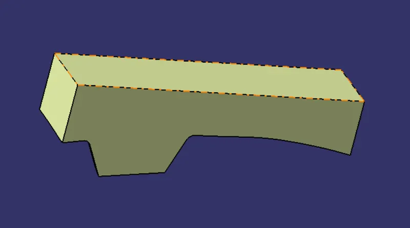
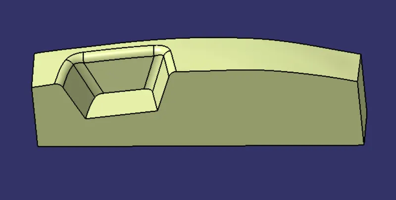
A core is the one part of the mould and it is responsible for the half of the molded part. Core is projection of the body and cavity is depression of the body. Thse core and cavity combines to form a mould. Plastic material is injected into the mould to het the plastic part.
Parting surface:
Injection mold has two major components one is core and other is cavity. During the injection molding process, these two halves are pressed tightly from a sealed hollow to avoid the melt flow leakage and maintain certain holding pressure, the pressed surface are called Parting surface.
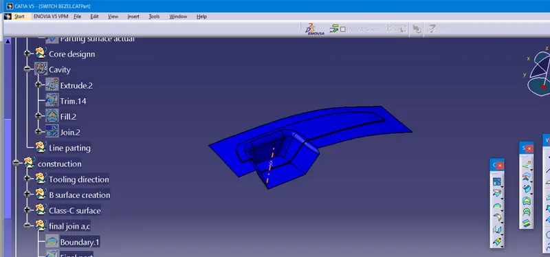
Parting line:
It is the area at which parting surface anad component meets or it is a juction between core and cavity.
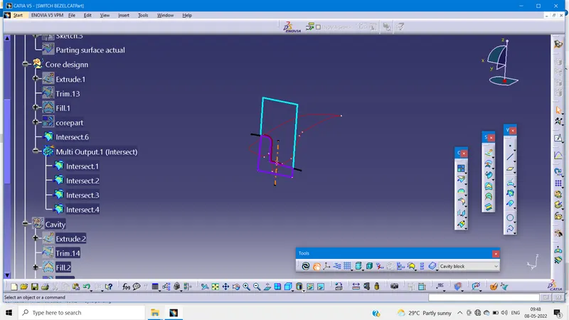
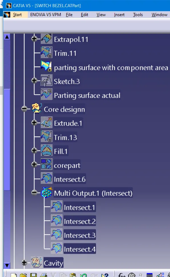
Core design:
Extrapolate class-A surface
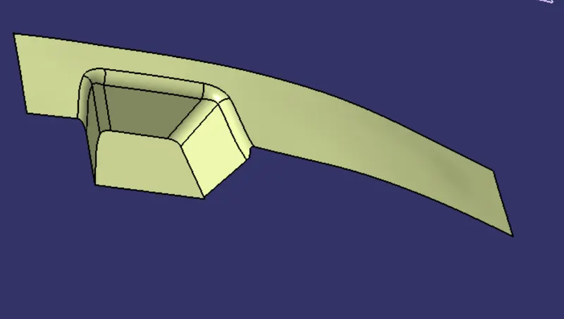
Trim class-A with Class-C to get inside portion
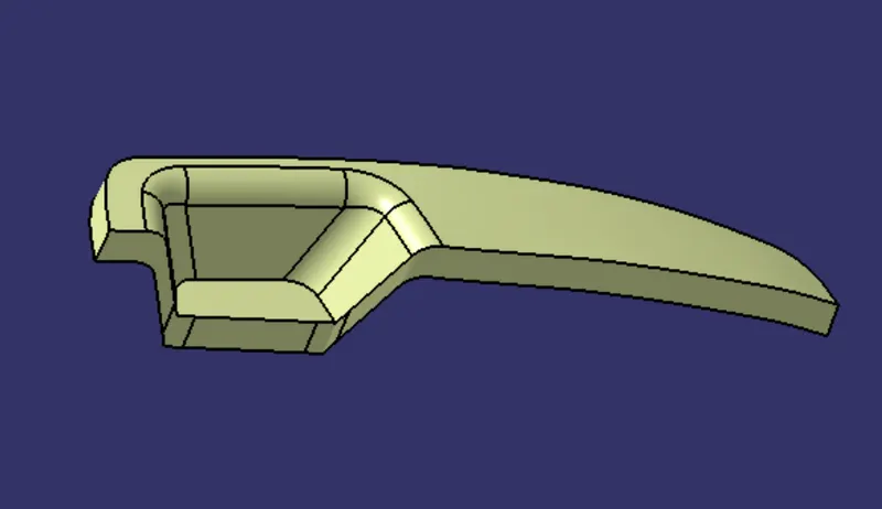
Now, trim the B-surface with output of class-A and C that will be parting surface with respect to the area. Extrude the sketch overall through the tooling direction. And trim it with parting surface.
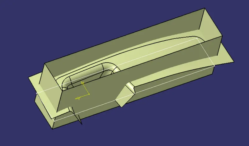
Final output of core design
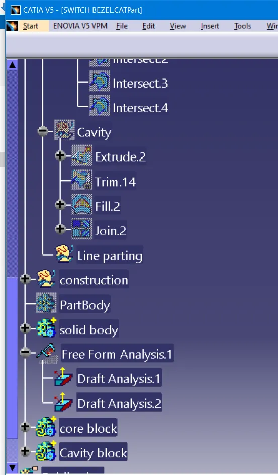
Similarly, repeating the same as done for cavity part and trim it on the other side surface.
Part body of cavity
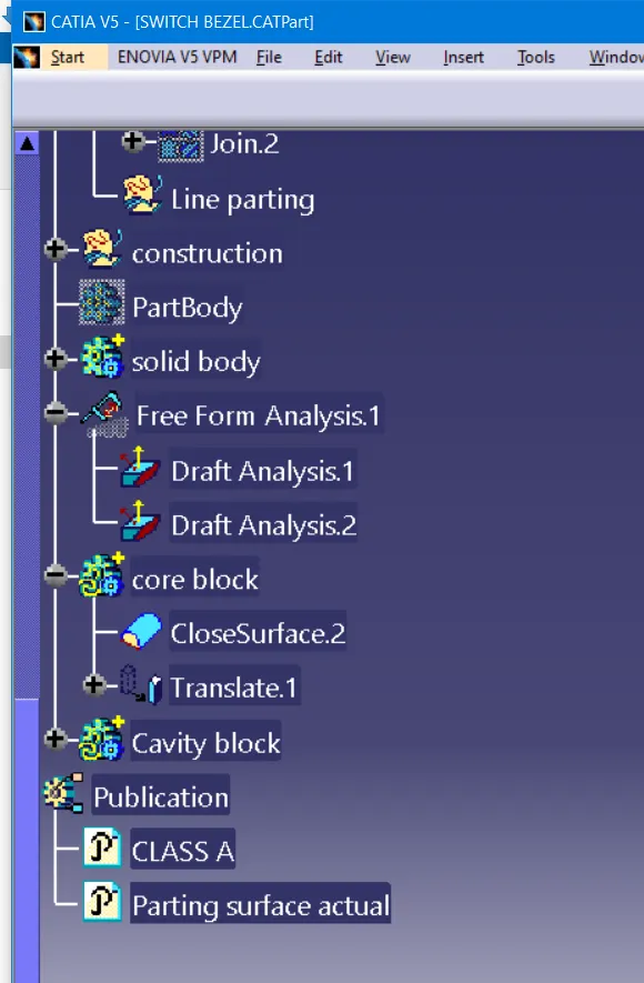
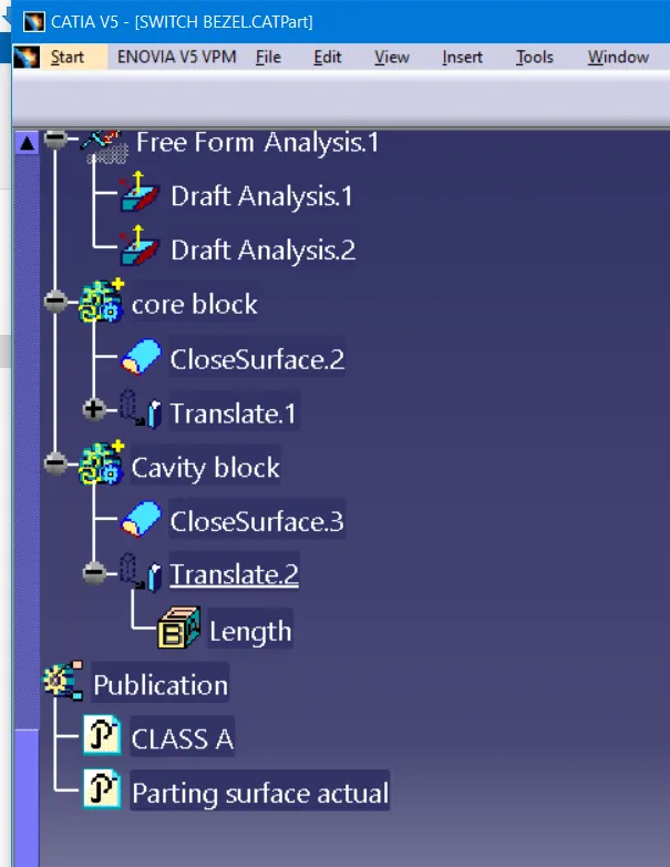
Core and cavity translated to certain distance.
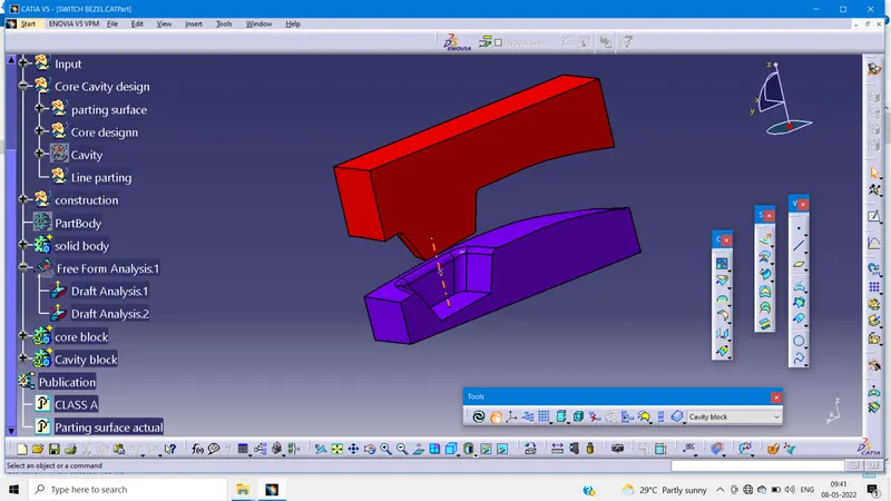
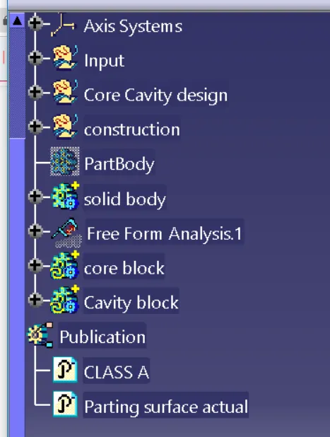
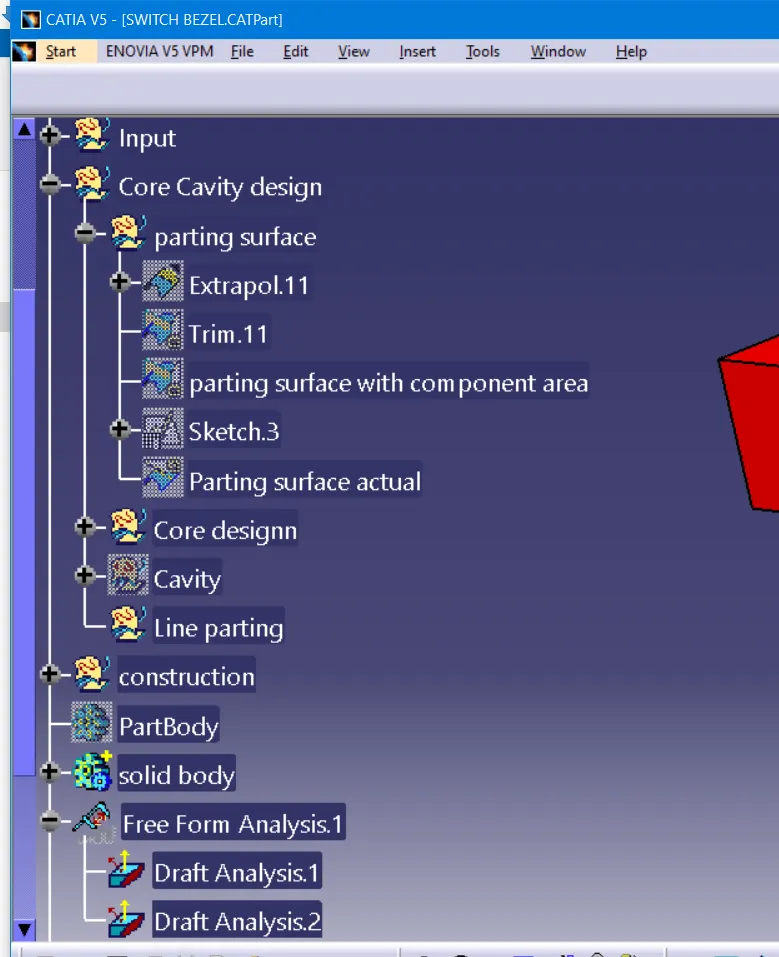
Result:
Core and cavity for the switch bezel has been created as per the design rules.