Week 8 - Challenge 5 - Core & Cavity Design
Core & Cavity Design
Aim: To create the Core and cavity blocks for the switch bezel.
Draft analysis
The Draft Analysis command enables you to detect if the part you drafted will be easily removed. This type of analysis is performed based on color ranges identifying zones on the analyzed element where the deviation from the draft direction at any point, corresponds to specified values.
Tooling axis creation
The direction in which the mold or core and cavity opens is the tooling axis. And for that the model is visually analyzed to know which is the most suitable direction for tooling axis. After analyzing the direction, we can create dummy tooling axis, with the help of each walls of the component. Then by bisecting method, that is bisecting the dummy tooling axis, we can find the real tooling axis.
Core & Cavity
The core & cavity are the shaped sections in either half of the mould tool which give the plastic product its final shape. The hot molten material is injected into the core & cavity and then sets hard into shape. The design of the core & cavity is essential in the correct formation of the product. The core is the male part which forms the internal shape of molding. The cavity is the female part which forms external shape of molding.
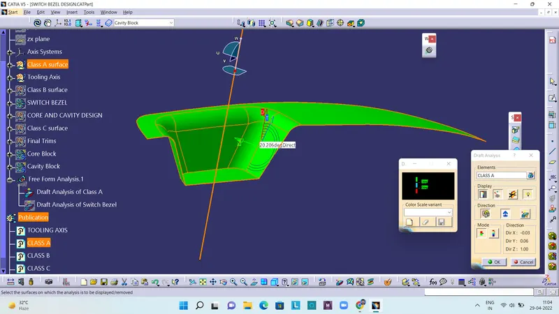
Draft analysis report of Class-A surface
The below figure shows the draft analysis report for the given Class A surface. The blue colour zone shows that there is 0 draft angle.
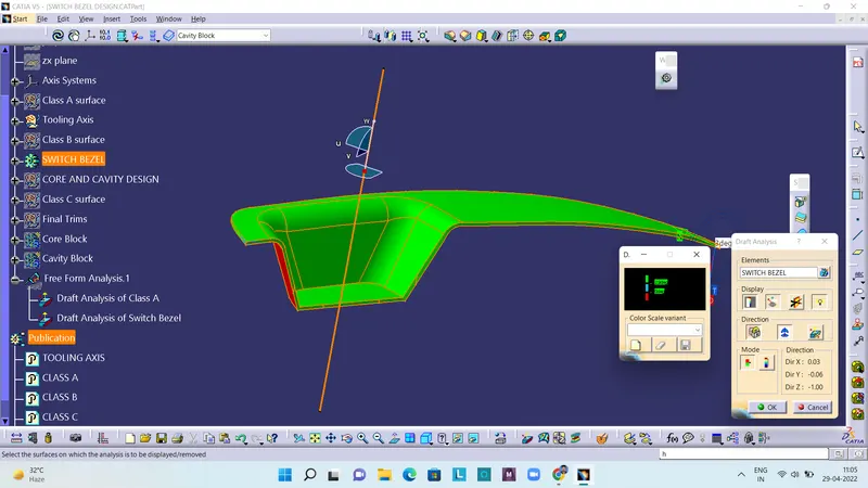
Draft analysis report of the final plastic component
The below figure shows the draft analysis report for the final plastic component. The blue colour zone shows that there is 0 draft angle, and the red coloured region shows there is negative draft angle.
Core Block in various orientations
Isometric View:
Front View:
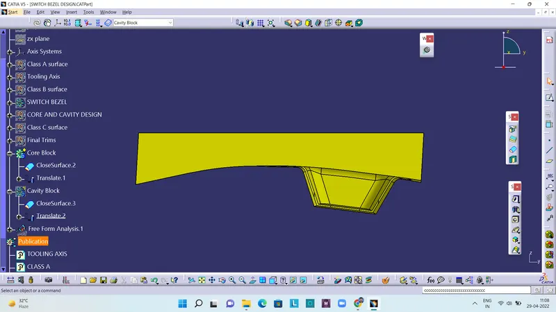
Side View:
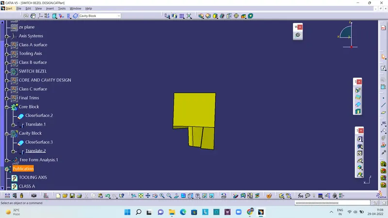
Top View:
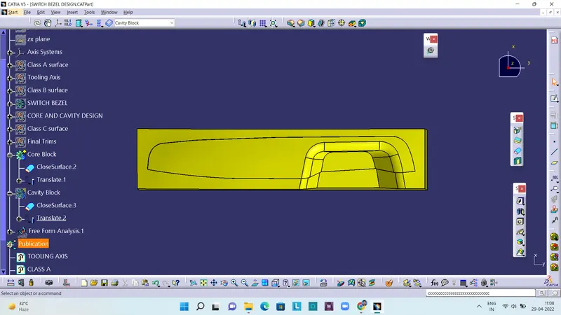
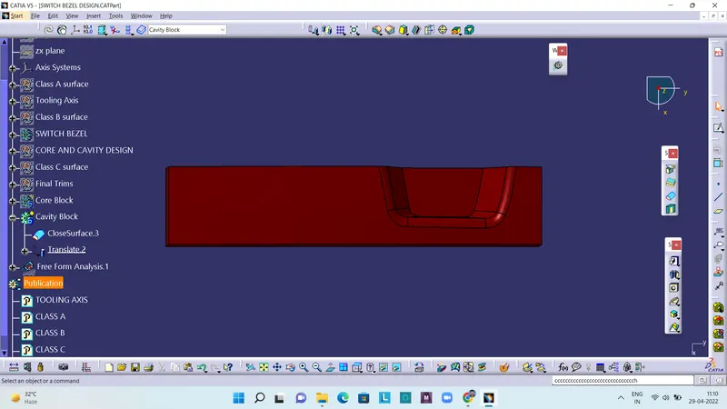
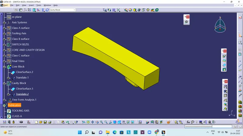
Cavity Blocks in various orientations
Isometric View:
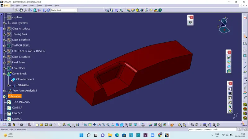
Front View:
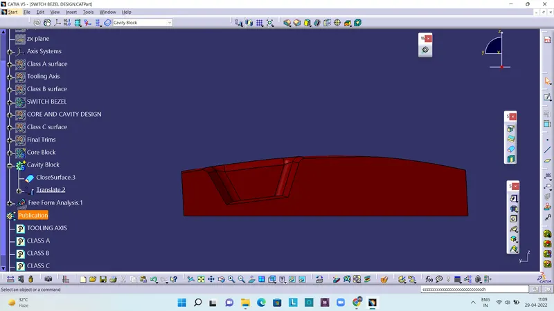
Side View:
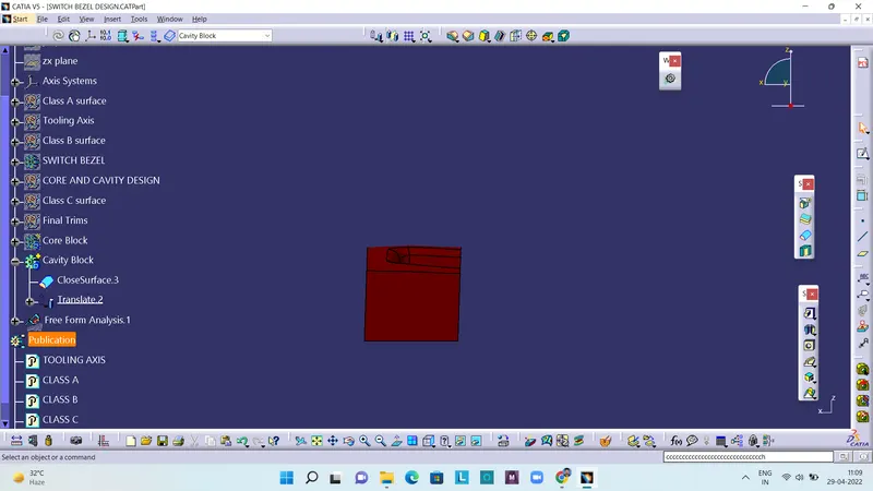
Top View: