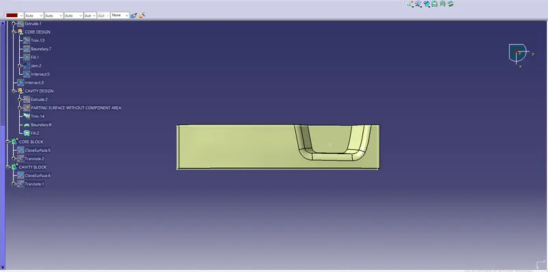
Week 8 - Challenge 5 - Core & Cavity Design
SWITCH BEZEL:
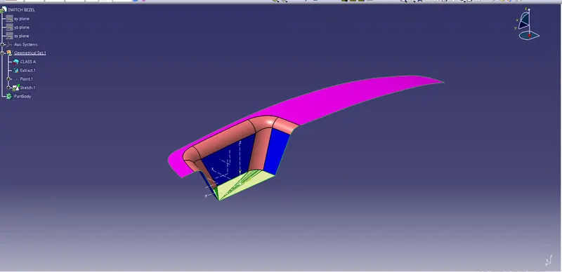
DRAFT ANALYSIS OF SWITCH BEZEL:
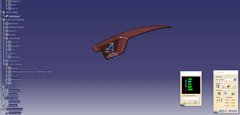
- Choose the customize toolbar and select materials in that toolbar.
- Insert Analysis, feature draft anlysis.
- Select compass in draft analysis and place it on the Tooling axis to coincide.
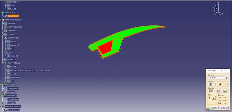
- In display Toolbar in draft analysis shoes the degree green as 3 , red as zero & blue is negative.
- In full analysis mode gives us every angle which is displayed below.
LET US DESIGN A CORE & CAVITY FOR THE SWITCH BEZEL COMPONENT:
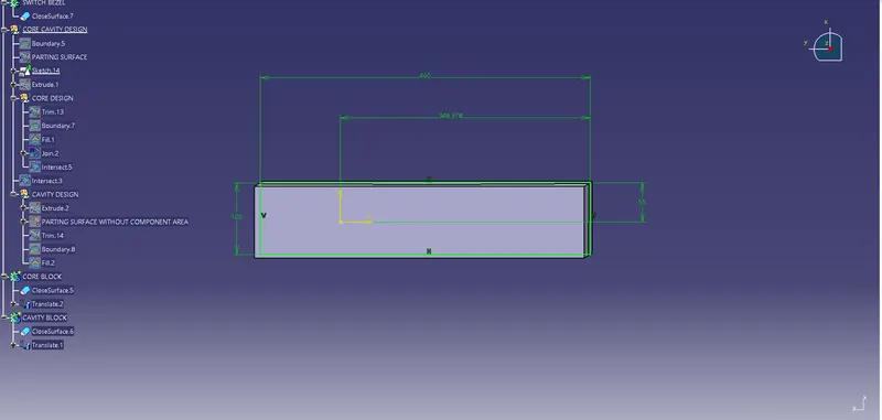
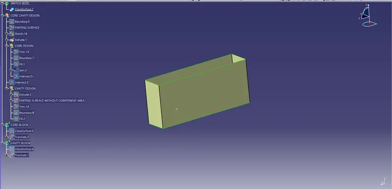
- Intially Insert a geometrical set & name it as core cavity design
- Put a boundary in the part.
- Create a parting surface.
- Put a sketch and Extrude the sketch.
CORE DESIGN
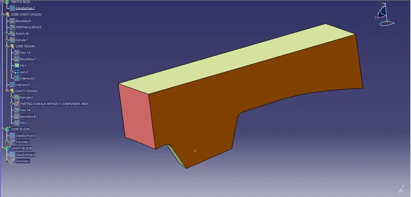
- Next Insert a geometrical set & name it as core design.
- Trim the parting surface and extuded component.
- After trimming using Fill command Fill it.
- Finally Join it then core is created.
CAVITY DESIGN:
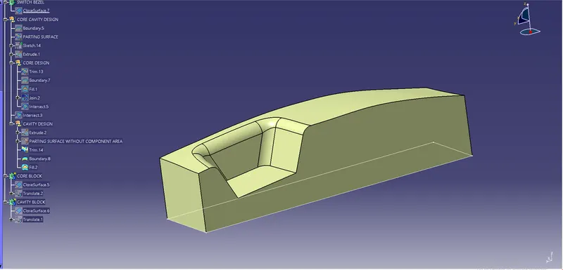
- Intially craete a Extrude between the tooling axis and sketch.
- Create a parting surface without component area.
- Trim the Extrude & parting surface without component area.
- Create the boundary for that component.
- Fill the boundary & cavity has been created.
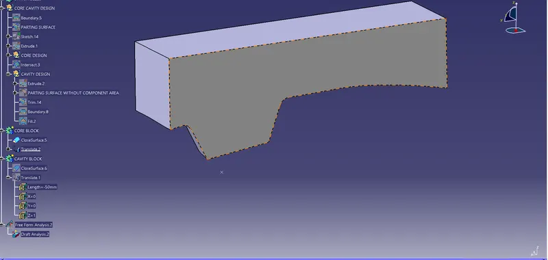
CORE BLOCK:
- Intially switch on to part design workbench and make the core as solid body.
- Translate it to 50mm.
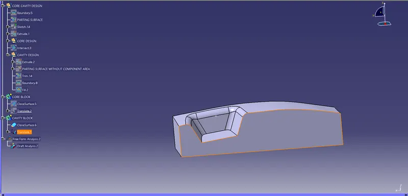
CAVITY BLOCK:
- Intially switch on to part design workbench and make the cavity as solid body.
- Translate it to -50mm.
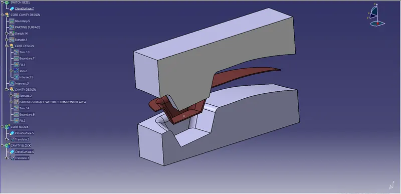
CORE & CAVITY FOR SWITCH BEZEL FINAL COMPONENT:
- Unhide the Switch Bezel component.
- Unhide the core.
- Unhide the cavity.
- Core & Cavity is created For Switch Bezel Component.
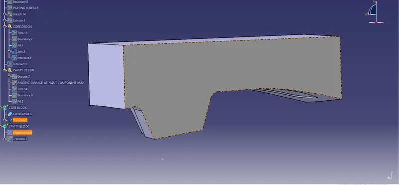
Isometric view of Core & Cavity:
Core:
Cavity:
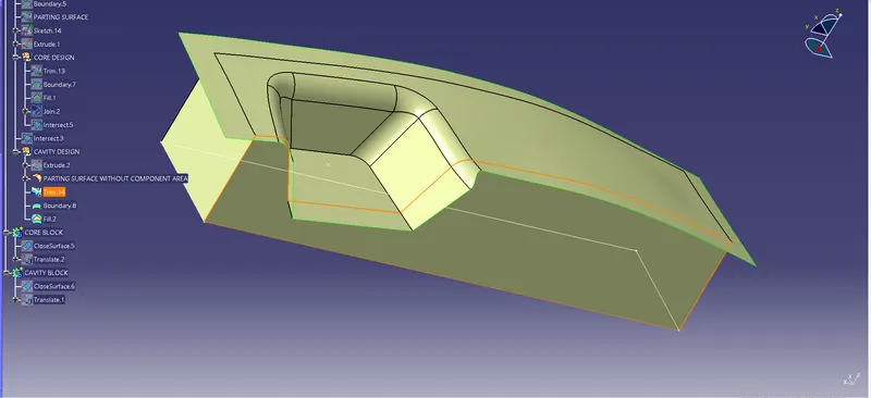
Front view of Core & Cavity:
Core:
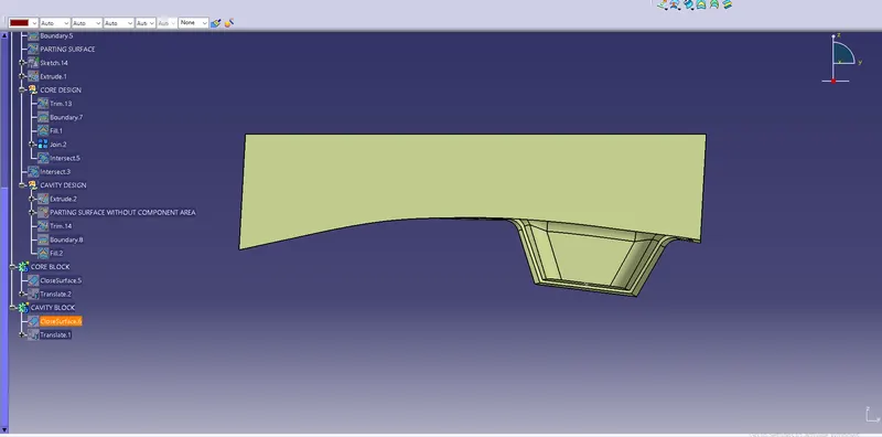
Cavity:
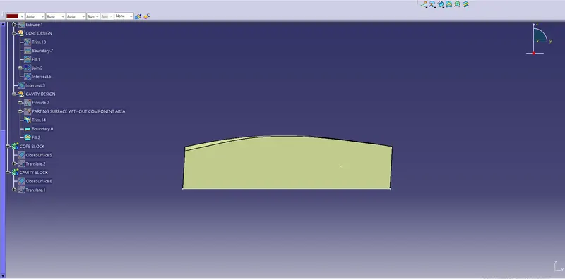
Top view of Core & Cavity:
Core:
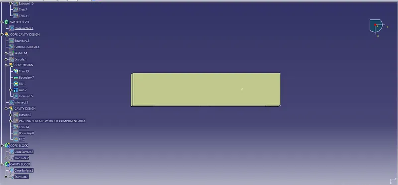
Cavity: