Week 8 - Challenge 5 - Core & Cavity Design
AIM: Design a core and cavity for the switch bezel.
CORE & CAVITY: The core & cavity are the shaped sections in either half of the mould tool which give the plastic product its final shape. The hot molten material is injected into the core & cavity and then sets hard into shape. The design of the core & cavity is essential in the correct formation of the product. Generally injection mold has two major components , They are the movable halve and the fixed halve, during the injecction molding process, these two halves are pressed tightly from a sealed hollow to avoid the melt flow leakage and maintain certain holding pressure, the pressed surface are called parting surface, usually parting surface are the biggest projection outline of the part. Parting surface design directly affects the product quality, ease of construction and operation of the injection mold, the mold design is one of the key factors to success.
PARTING SURFACE: The parting surface of a mould are those surfaces of both mould plates adjacent to the impressions which butt together to form a seal and prevent the loss of plastic material from the impression. The various factors to be considered while selecting the parting surface are Shape of the Components, Type of Mould, Method of Ejection, Method of Manufacture, Location and Type of Gate, Aesthetics of moulding. In general the parting surface is classified into two types, they are Flat parting surface, Non-flat parting surface.
DESIGN OF CORE AND CAVITY FOR SWITCH BEZEL:
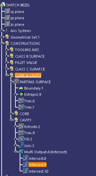
- 1st create the parting surface for the CATPART, core part and later cavity part.
- Take the A surface and extrapolate the A surface using extrapolate tool and boundry tool.
- Now take the C surface and trim the C surface from the A surface.
- Now take B surface and trim from the trimmed surface of AC surfaces. This is our parting surface.
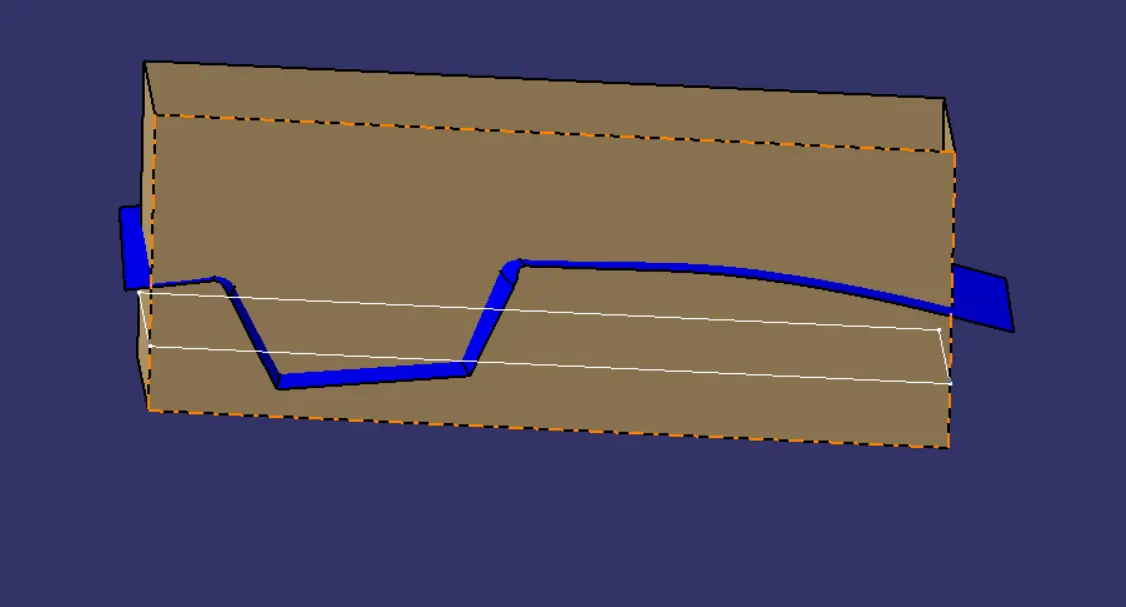
- Now designing the core part, by selecting a plane go to exit work bench and take a rectangle which drawn on the switch bezel where the part is locating inside the rectangle with respect to the tooling axis.
- Now extrude the rectangle and trim it from the parting surface and fill the other side opening of the extrude part.
- Now join the fill the trim part.
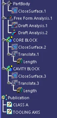
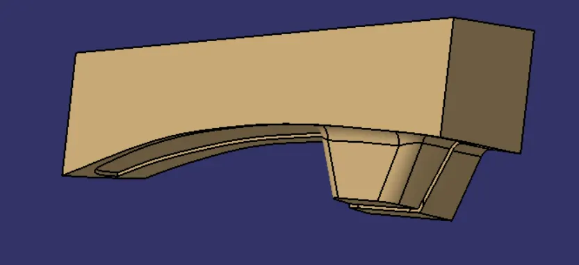
- now go to part design from generative shape design and create the solid part of the core with the help of the close surface.
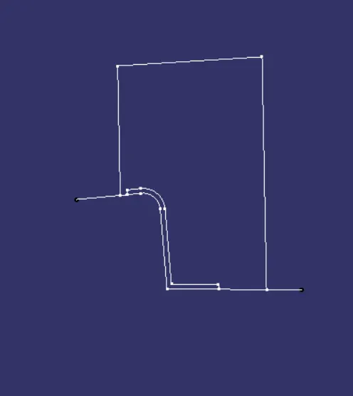
- Now take the intersection of the core and the parting surface with the help of intersection tool.
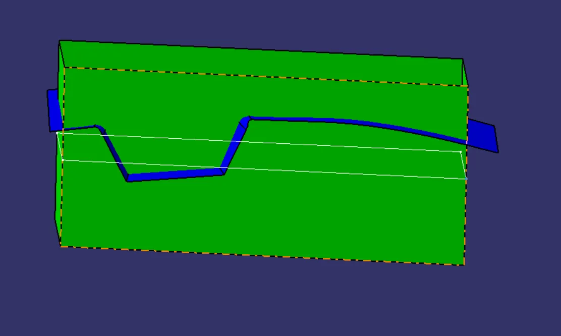
- Extrude the rectangle which used to create the core part along the axis and trim the top section of the extrude to the parting surface.
- Repeat the same process similar to the core upto the close surface.
- Create a intersection od the core cavity and the parting surface.
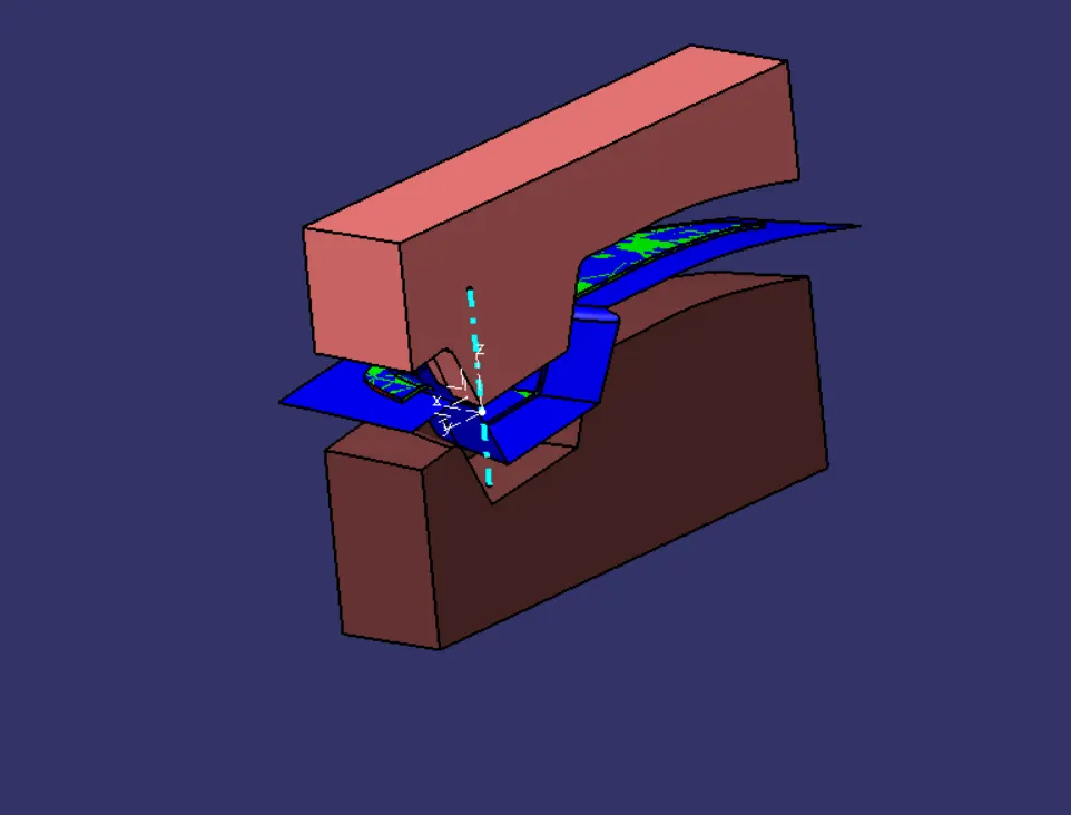
- Now by using transulation tool divide the core, parting surface, and the cavity.
Stepwise Drawings of the Design of core and cavity:
Class A surafce:
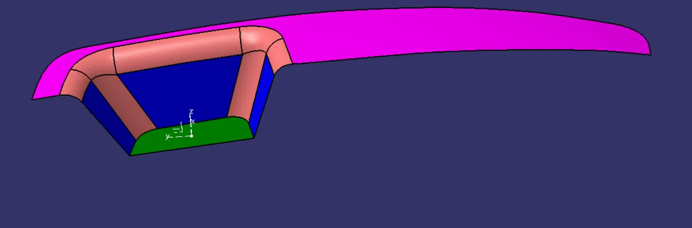
Extrapolated Class A surafce:
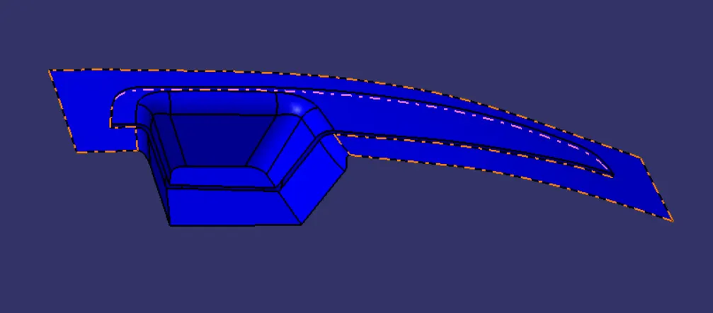
Class C AND A surfaces:
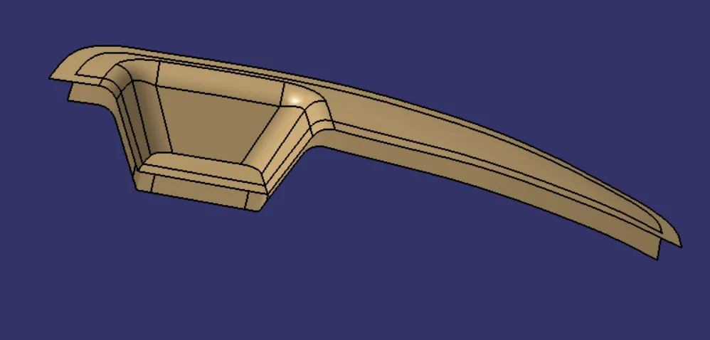
Trim1:
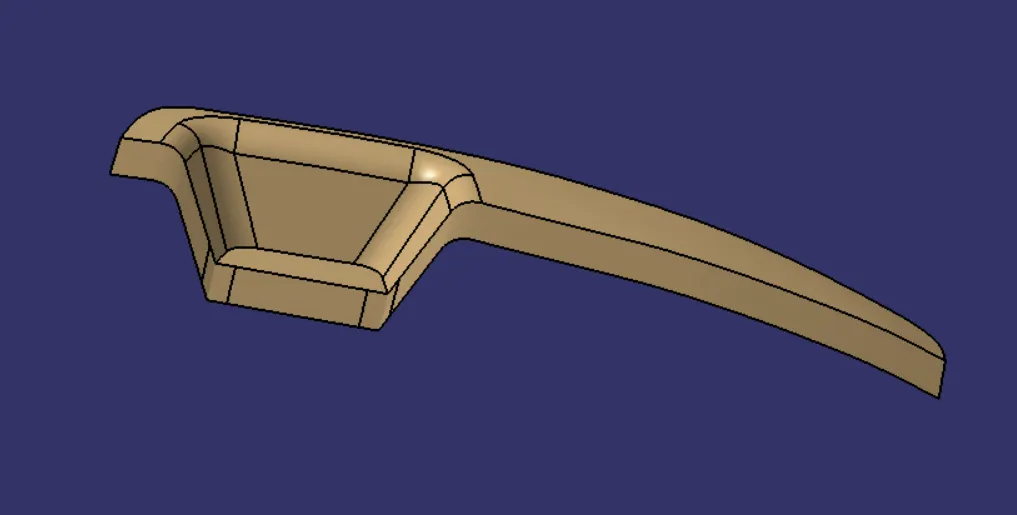
Class B surface:
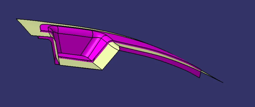
Parting surface or trim2:
core part:
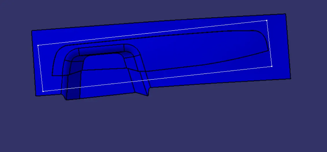
Intersection:
Cavity part:
CORE AND CAVITY:
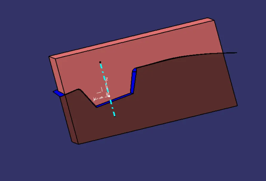
Overall intersection:
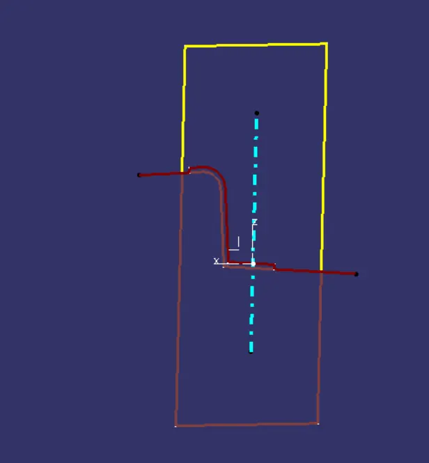
Translation:
TREE: