Week 8 - Challenge 5 - Core & Cavity Design
Aim:
To create the core and cavity on the switch bezel.
Core and Cavity
The core is the male part which forms the internal shape of molding. The cavity is the female part which forms external shape of molding.
Parting Line
A 'parting line' is the line of separation on the plastic part where the two halves of the plastic injection mold meet. The line actually indicates the parting 'plane' that passes through the part. The line or plane along which sections of a foundry mold, die, or pattern separate.
What is the purpose of a parting line?
A parting line is a borderline in which draft angles change direction or a dividing line that splits the core and cavity halves of a molded part. It can also be used as a starting point for the mold parting surface.
Procedure:
At first open the class A surface and select the boundary. After that extrapolate it .
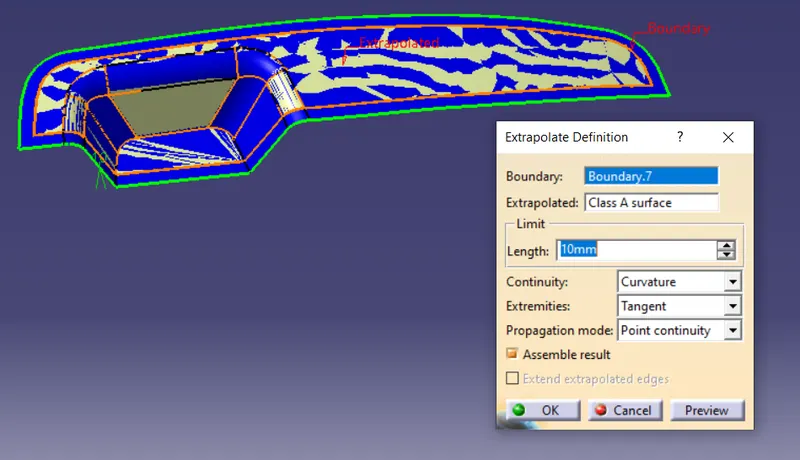
After extrapolate open the surface of class C and B with the extrapolate surface. After that trim the class A with the class C. And trim again with the class B and class C. Now gets a component.
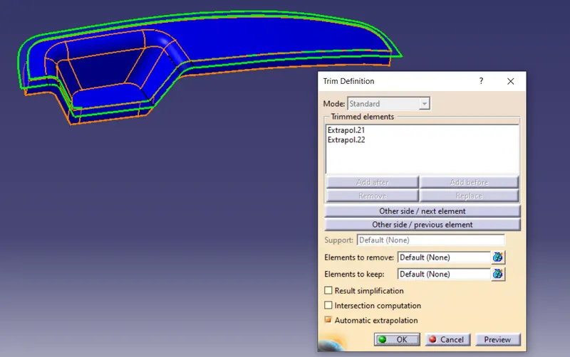
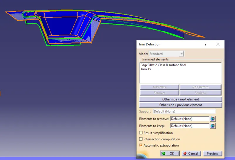
Now for creating the core and cavity. Draw the rectangle on the component. Now extrude with the sketch and the tooling axis. After extrution trim the surface with the parting surface. The above core part is designed.
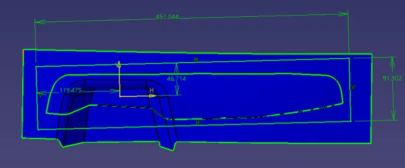
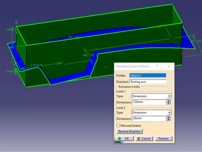
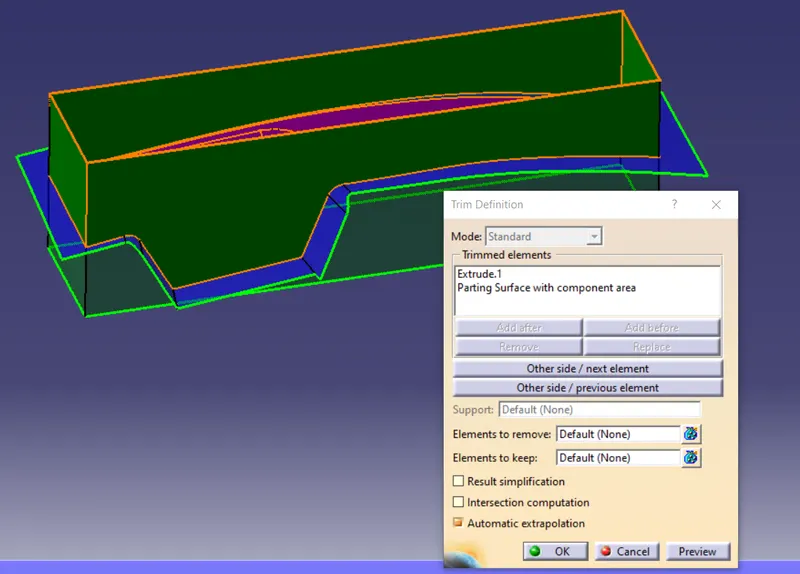
The same step is followed in here to. Here it is trimmed for the cavity part. After creating the core and cavity part intersect both the part with the intersection option(core, cavity and the parting surface).
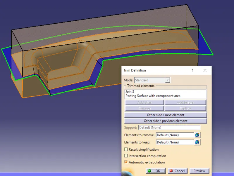
After that creating the intersection for the parting line. For that select the B surface and the C surface an parting line creates.
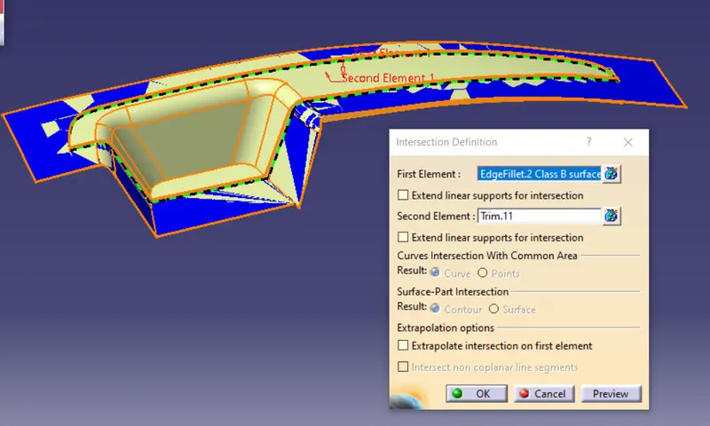
The final image of core and cavity. The translate in done in the part design with the tooling axis as in the image.
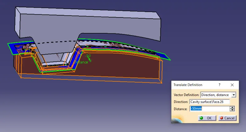
Final image
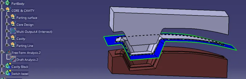
Result:
The core and cavity is designed with the switch bezel. The above image shows how the switch bezel is molded.