Week 8 - Challenge 5 - Core & Cavity Design
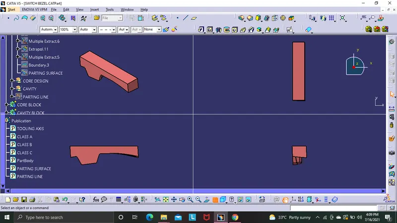
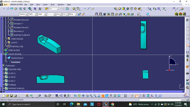
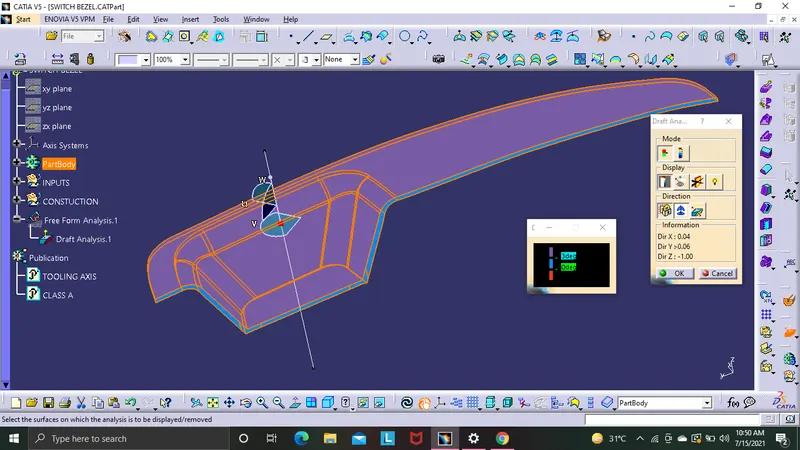
After completing the switch bezel in solid model go to generative shape design and then go to insert then select analysis then from there select feature drat analysis . before that select the custamised view to material mode amnd after that select the analysis under the running point and place it on the tooling axis and then ude the lock option to lock it then an re colour cross apears nd selct that on the model amd oit shows the display model and frm there select the colour model and change the draft to 3 deg and thus the draft analysis is checked
tooling axis creation
after using joint comment to joint the class A surface select the correct place to be used for manufacturing and at that base select a center point then place the axis system in it after that ytake the inter section on the class A by yz direction after that elonagte the vertical lines and then take bisect of the two line and create the dummy tooling axis on the YZ direction . same way take the tooling directuion for ZX direction but in here only one side is ther so take the nxt line from the center point. after that give the value of 3 deg ( later the value is adjusted ) and the dummy tooling axis ZX is created . now take bisecting line on both YZ and ZX tooling direction and thus the tooling axisd is created