Week 8 - Challenge 5 - Core & Cavity Design
GENERAL DESCRIPTION-
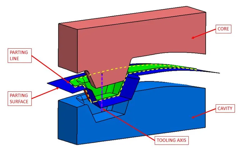
Screenshots of the core and cavity blocks in various orientations (Isometric, Front, Side, and Top View)
ISO-
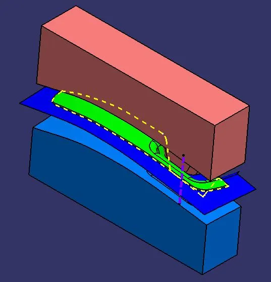
FRONT-
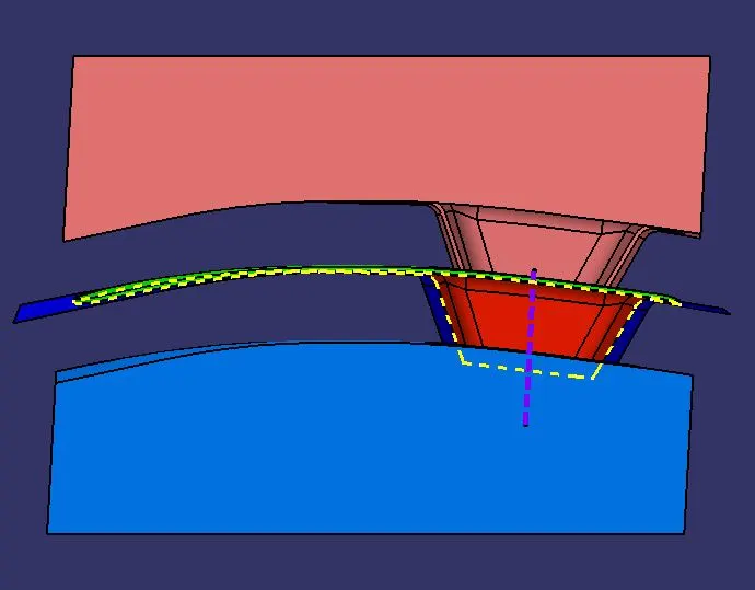
SIDE VIEW-
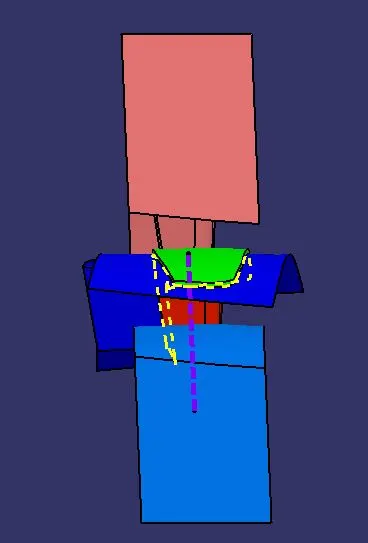
TOP VIEW-
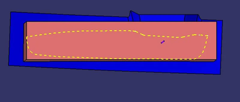
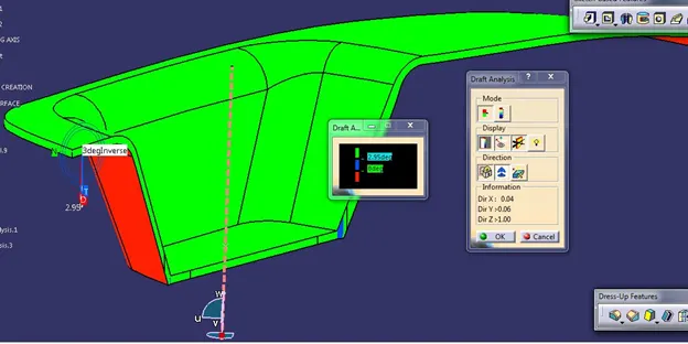
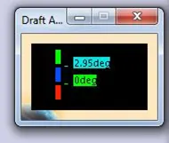
Screenshots of the Draft analysis report for both the switch bezel plastic component-
Procedure for Tooling Axis Creation-
- Check the basic checks before starting. Check connectivity of Class – A using Join or boundary operation and ensure that there are no gaps in the Class-A. Perform initial checks to check for incomplete patches.
- Look at the component and check the sides for the best fit as per the axis according to the XYZ of the vehicle that are most suitable as tooling direction, imagining them considering tool movement and side core minimization requirement.
- Create a geometric set for Tooling axis creation. We create a dummy tooling axis to help us imagine the XYZ of the vehicle using a point or a plane, one that is derived from a hole or with reference to component itself.
- Create 2 intercepts using axis System planes XZ and YZ, i,e., along x and y directions. Make the position sketches accordingly making sure that all faces are clearing dummy Tooling. Use the Bisection method to create Tooling axis along x and Y direction using faces that you think that might create problems.
- We can Create a dummy tooling for our reference while Working on Bisection Method. Use the dummy Tooling axis to check whether all the Faces made using intercept clear the dummy axis.
Faces Perpendicular (90 deg) with Dummy tooling- definitely clear
Some Face Visually they look they will Clear but we have to cross check with the tooling analysis.
The Problem comes with Parallel Face (at zero deg) or negative face (less then zero).We have to check for draft analysis and check whether they clear the tooling axis or not. We have to ensure that they are Positive.
6. Bisecting method on XZ plane-
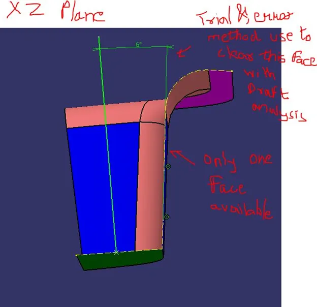
Using the axis system on the XZ plane, Identify the faces that may create problems. Here there is only one face and not two like earlier example. So we have to use a different method.
Take a reference Point usually using a circle or base plane center.
Extend those faces and use extended lines.
Draw a line sketch at a minimum angle required to provide a draft for a plastic component, i.e., minimum 3 deg to find the axis(bisecting line). Trial and error to check at which angle the problematic face clears the axis on the XZ plane. Name is as Tooling clearing X direction.
7. Bisecting method on YZ plane-
Using the axis system on the YZ plane, Identify the faces that may create problems.
Take a reference Point usually using a circle or a base plane center.
Extend those faces and extend lines.
Use Bisecting Lines to Find the axis(bisecting line) that will clear the two problematic faces in YZ plane. Name is as Tooling clearing Y direction.
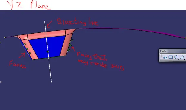
8. Use the intercepts with the x and y directions to get line representing tooling clearing x direction and tooling clearing y direction. This will help us to help locate the tooling axis by bisecting these two lines representing x and y tooling directions.
Create a Bisecting Line using the Tooling clearing X-direction line and Tooling clearing Y-direction line. Renaming the resultant bisecting line as Tooling Axis. Publish Tooling axis and A surface.
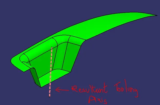
Resultant tooling axis created using the X and Y intercepts Axis lines.
Procedure for Draft Analysis-
Step 1- Change the viewing mode to material mode.
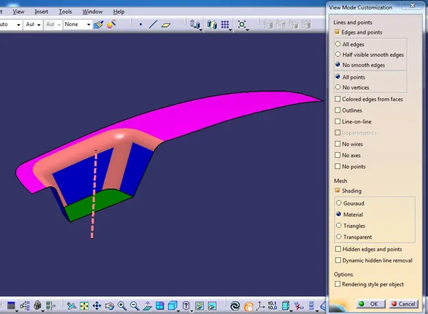
Step 2- Click on draft Analysis and Select use the compass option to mount the Compass on the Tooling Axis.
Step 3- Select the Lock the draft option from analysis tool window and click on the Face of the component for which draft analysis is being carried.
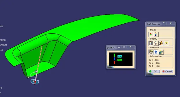
Step 4- Set the Range and colour of Draft to set the ranges and colour codes of the draft.
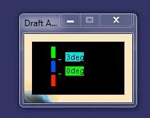
Step 5- Check the Inverse direction option for the mold opening and closing side as per your requirement
Step 6 - Use Analysis under the running point Option to check For The draft angle at a particular area which shows particular defect as per the colour code ranges.
Perform and check the draft colour scale gradient by setting parameters and perform draft analysis of the Class-A surface. If the component is clearing the tooling direction it will be displaced in a uniform colour (green) indicating that the surface will clear the tooling.
Draft Analysis of the Thickened Plastic Component-