Week 8 - Challenge 4 - Coin Holder Design
COIN HOLDER DESIGN
AIM:
Create the coin holder plastic component through the given class-A surface.
CLASS-A SURFACE:
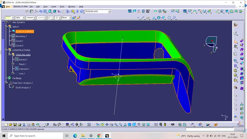
This is the given class-A surface which is used to create the class B and C surfaces.
TOOLING AXIS:
The first step in creating the other surfaces is the construction of the tooling axis.
- Extract the base surface from class-A surface.Create a point on the extracted surface using the point command.
- Create a new axis system using the above point as the origin and create a line normal to the surface.The line is the tooling axis which is coloured brown for easy visualization.
PUBLISHING:
- Go to tools and then publishing,select the class-A surface and the tooling axis to publish.
CLASS B SURFACE:
BASE:
- Class B surface is created using the class A surface.Firstly,extract the side of the base from the class A surface.
- Untrim the surfaces.Extrapolate the above surface using curvature continuity and point continuity.Trim the surfaces together to get a single surface resembling the base in the class A surfaces.
- The thickness of the component is 2.5mm.So the above surface needs to be offset to a distance of 2.5mm.
SIDE WALLS:
- Extract the sidewall surfaces from the class-A surface.Untrim the above surfaces and extrapolate them using curvature continuity and point continuity.
- Trim the surfaces to get a single surface that resembles 4 enclosing walls.This surface all needs to be offset for a distance of 2.5mm outwords beacuse of the thickness of the component.After trimming,provide fillets to the edges according to class A surface and the thickness.
UPPER WALLS:
- Extract the upper wall surfaces from the class A surface using the Multi Extract feature including the fillets.
- Extrapolate the above surface using point and curvature continuity and create an offset of 2.5mm outwords.
OUTER FLANGES:
- The outer flange surface needs to be created in two steps.Firstly,extract the enclosing surface from the class A surface.Extrapolate the above-extracted surface using the curvature sand point continuity
- Now,extract the remaining surfaces of the outer flange from the class A surface.Untrim the above-extracted surfaces and join them using the join feature and then extrapolate the resulting surface.
- Creates offsets of the above surfaces.The offset needs to be created inwards because the outer flange surface in class B surface will be below the outer flange surface in class A surface.
- Finally,trim the surfaces together and provide a different colour to the resulting surface.
PAD:
- In class A surface,there is a small pad.For class B,the walls of the pad need to be extracted from the class A surface.Untrim the aabove surfaces and extrapolate them using the curvature continuity and point continuity.Create an offset of the above surface and provide it with a different colour.
INTIAL TRIMS:
- Trim the base and the sidewall surfaces first,using the trim feature.Trim the above surface and the top wall surface together using the trim feature.Now,trim the above surface and the outer flange surface together using the trim feature.Extract the small flat surface at the top from the class A surface.Untrim the extracted surface and extrapolate it from all four boundaries.
- Offset the extrapolated surface to 2.5mm and trim it with the last trimmed surface.Finally,trim the above surface and the pad surface using the trim feature.
CLASS C SURFACE:
- Extract the enclosing walls of the outer flange using the mutiple extract feature.Extract the boundary of the class A surface.Use the sweep feature,with subtype as with refernce surface.Choose the guide curve 1 as the above-extracted boundary and the reference surface from the class A surface.Choose the angles as 90 degrees.
- Now the class C surfaces for the section needs to be created.Extraced the boundary of the section and nearby surfaces.Again use the same sweep command with the same subtype and angle.Choose the guide curves ass the extracted boundary and the refernce surface as above-extraced surface.Following are the class C surfaces.
PART BODY:
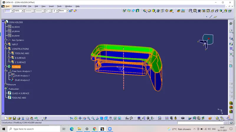
Firstly,trim the class B surface and the class C surface of the section.Now, trim above surface and the other class C surface.Finally,trim the above surface and the class A surface to get the final enclosed surface.Use the close surface feature and it converted into a solid body.
DRAFT ANALYSIS:
- For the draft analysis,we need the solid body and the tooling axis.Customize the view parameters to change the mesh shading to the material.
- Choose the compass from the above dialouge box and drag-and-drop it on the tooling axis.Choose the solid body as the element
CONCLUSION:
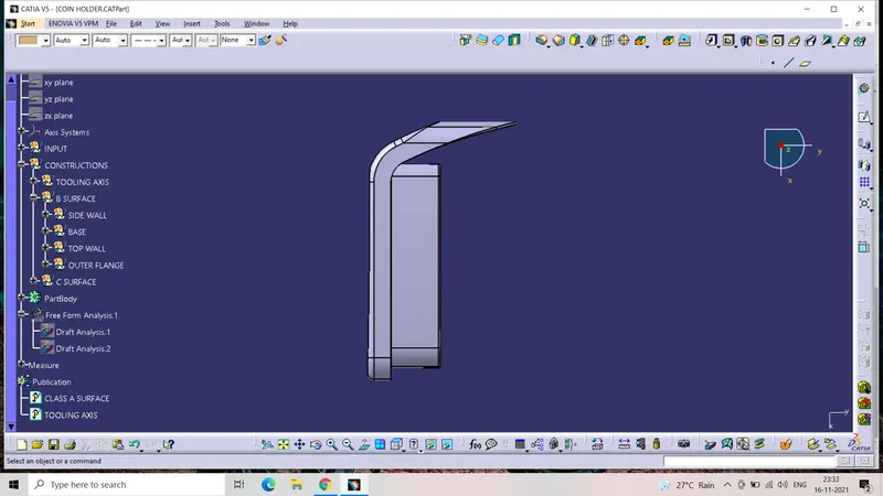
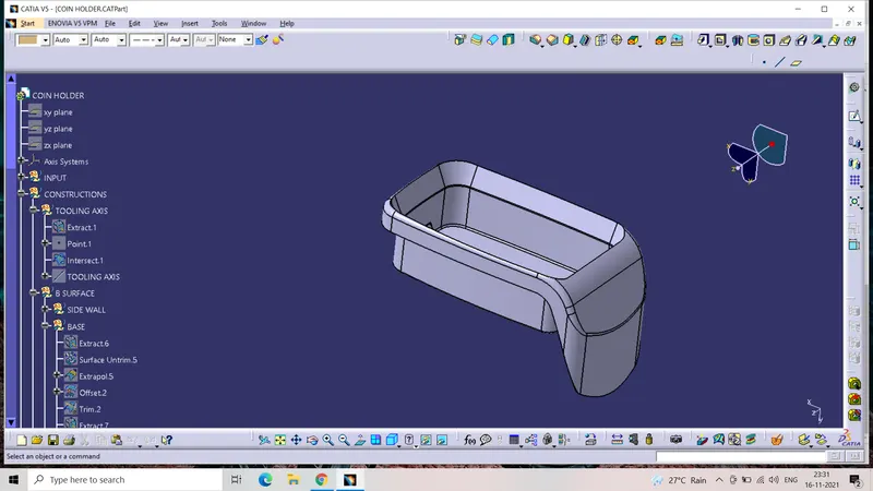
- The class B and class C surfaces are successfully created from the given class A surface.The class A,class b and class C surfaces are trimmed together to create the final close surface of the component.
- The solid body is successfully created using the closed surface,the draft analysis is successfully completed.
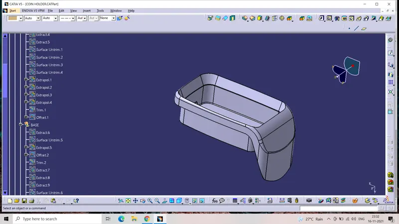
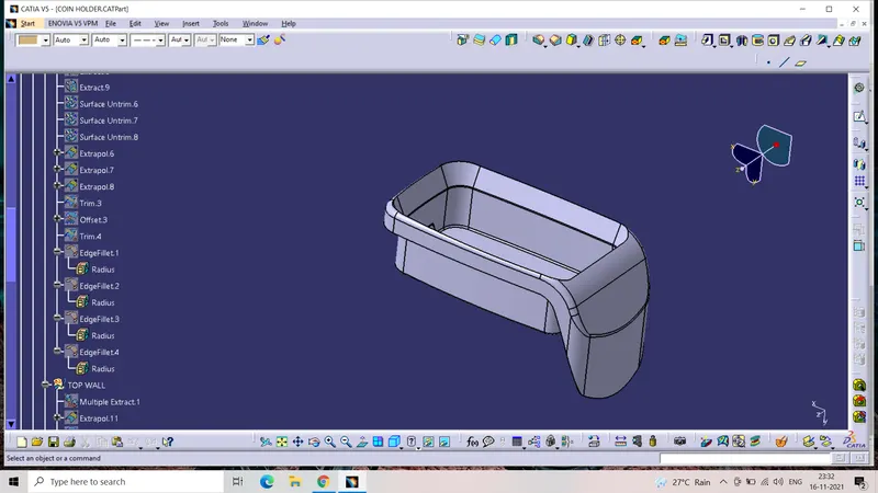
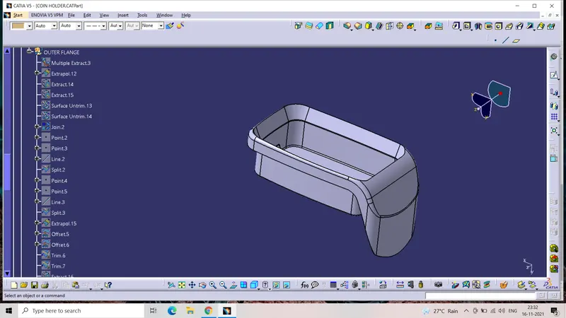
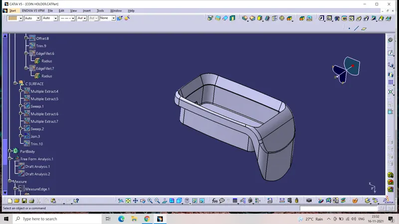
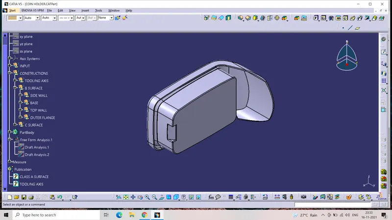
TREE STRUCTURE:
ISOMETRIC:
FRONT:
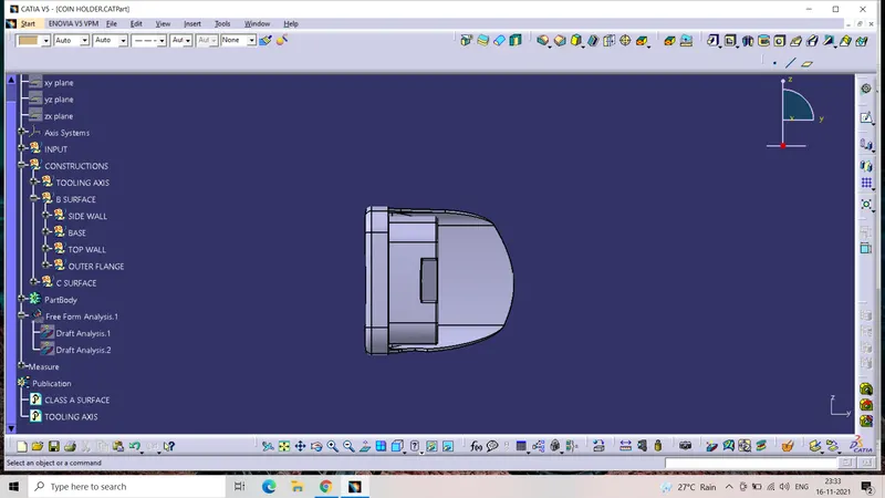
TOP: