Week 8 - Challenge 4 - Coin Holder Design
INPUT: Automotive Class-A surface, obtained from Autodesk Alias.
OBJECTIVE: Create Tooling axis for the given surface and carry out Draft analysis to meet the required minimum draft angle for plastic injection molding and to thicken to a thickness of 2.5mm throughout and again perform draft analysis for the final component.
Steps to create Tooling axis:
1. Initial step is to visualise the given input surface carefully so that all the surfaces clears during tooling at one go. While doing this, generally holes, large surfaces with less contours and flat land surfaces are preferred.
2. There are 3 Axis in a 3D part. i.e., X,Y and Z and 3 planes, XY, XZ and YZ. Next step is to "Intersect" the axis on the surface along one of the planes mentioned above leaving the axis along which the tooling axis will be created. Instead of using intersect option directly, There is an Axis system at a point which is the center of the base of the coin holder surface present in the CLASS-A Surface. The axis system is intersected along XY and YZ plane, where the tooling axis will be created normal to XZ plane.As it can be seen, the white colour curves running across the length and width of the surface is the intersects along XY and YZ plane.
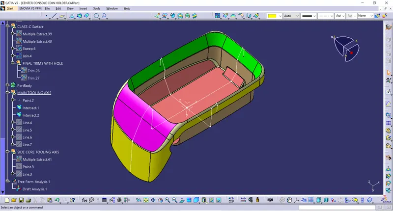
3. Next step is to create the lines using the drop down option stating "Point to Point" across the intersects created along the points where the surfaces creates problem for clearing the tool. The line so drawn are made sure to meet the minimum draft angle criteria of 3 degrees.
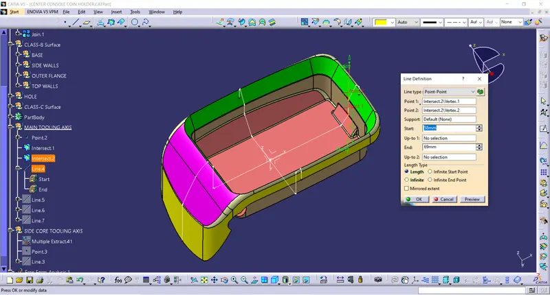
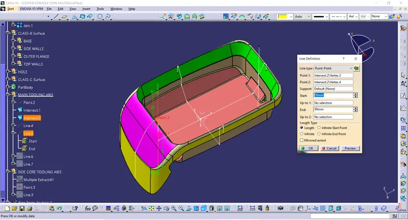
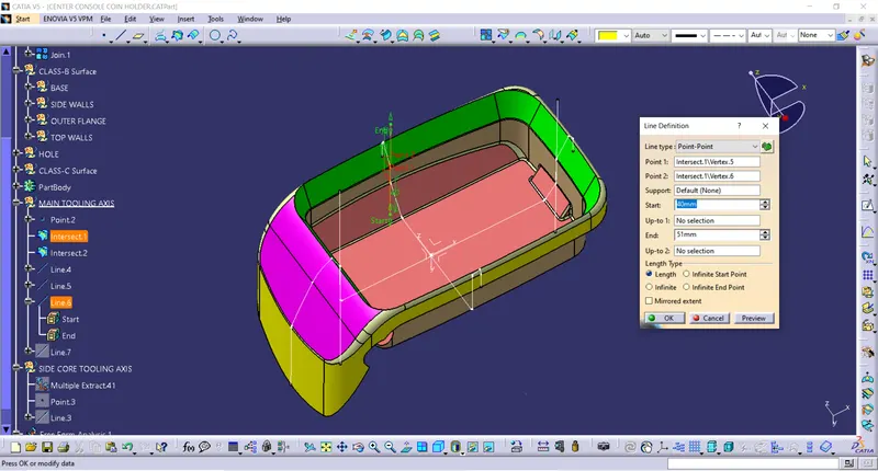
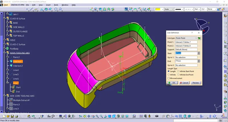
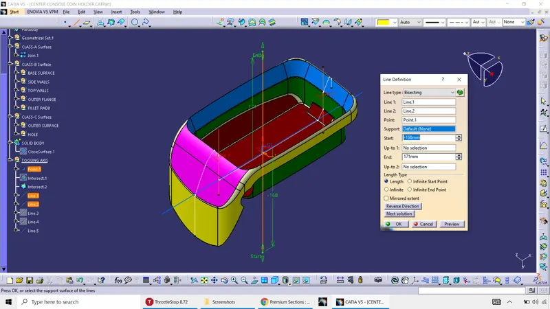
4. Next step is to create Bisecting lines across using the point to point lines created on two of those planes. In this method of creating the Bisecting line, there has be of two lines and a point. The resulting line is the mean of the two lines initially created and it passes along the point selected/created/. The lines created may not be parallel, have same angles on opposite sides and also bisecting lines with different direction along two non parallel or different planes of the initial two lines can also be created. But the primary focus is on the lines laying on same plane is used extensively. The point along which the resulting bisecting line passes can be selected if present or can be created seperately using various options, but "midpoint" option is preferred, so that the resulting point will be the mid point between the points at the extreme ends of the initial lines created.
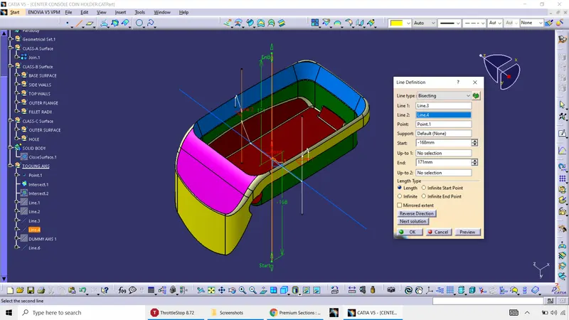
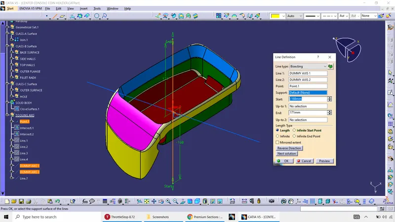
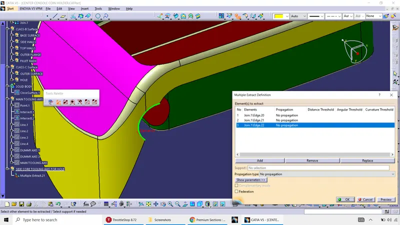
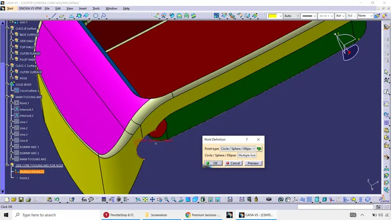
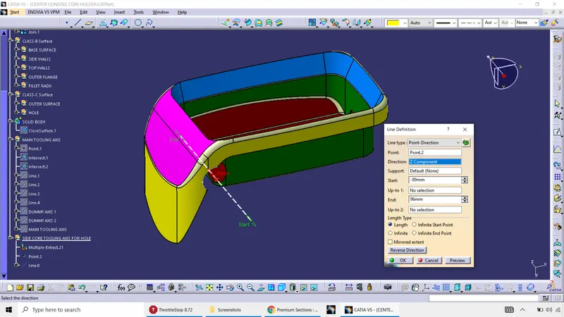
SIDE CORE TOOLING: It is provided in order to create features of the component which cannot be cleared with the main tooling. It is essentially application based features of a component. The axis provided to create the feature along the side core/cavity, is called theSide core tooling axis. In this particular example, the hole in the surface requires seperate tool to clear the component in the injection molding machine. Below are the screenshots of the steps taken to create it. Extract the circular curve, create a point at the center of the circular extracted curve and draw a line along Z axis with point to direction option.
DRAFT ANALYSIS:
Steps to be followed for draft analysis:
1. Initially View mode selection is selected for "Material mode".
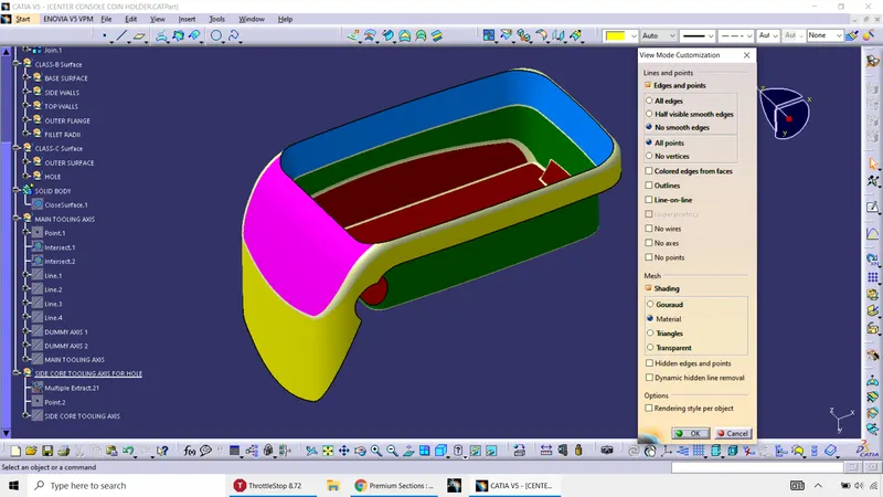
2. It is made sure that the workbench is "Generative Shape Design". Select the "Feature Draft Analysis" under the drop down menu in "Analysis" inside "Insert" option.
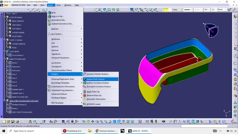
3. Select the "compass" option in the "Direction" and drag the compass, so that the "W" axis in the compass is inline with the Tooling axis. Lock the Compass on to the Tooling axis, using the lock symbol.
4. Next is to click on the part/surface on which the analysis is carried out.
5. The colour scale variant can be changed as per the needs.
Green colour represents, the draft angle meets minimum requirement and can be cleared.
Blue colour indicates the surfaces can't be cleared for the given minimum draft angle (3 degrees)
Red colour indicates the surface has negative draft angle.
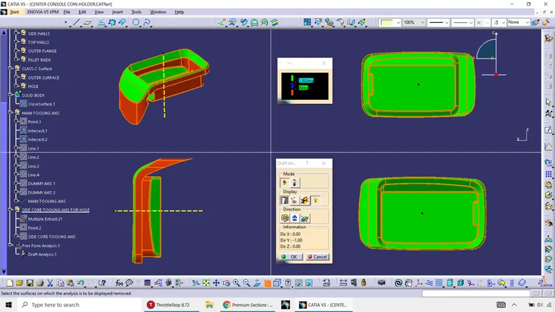
CONCLUSION FOR DRAFT ANALYSIS: Draft analysis has been carried out on the CLASS-A surface and is cleared along some of the surfaces as per the industry standard for further processes in an injection molding machine. Some of the surfaces have red colour in the Draft analysis, because the Class-A surface doesn't have minimum draft angle of 3 degrees. It is the job of the plastic part designer to communicate with the person who has created the Class-A surface to provide minimum draft angle, so that it can be cleared in main tooling.
CLASS B surface: It is the surface which is created parallel to each and every surfaces present in CLASS-A by offsetting the CLASS -A surfaces to a value which is equal to the final thickness of the plastic component.
STEPS TO CREATE CLASS-B SURFACE:
1. Initially, the CLASS-A surface needs to be observed/visualised carefully by the plastic part designer so as to begin creating the surfaces one by one. Precautions is taken so as to avoid fillets in the surface because it creates problems during offsetting the CLASS-A. Much focus is required on the large/flat surfaces and also surfaces with contours with holes.
2. Next step is to extract surfaces one by one from the CLASS-A.
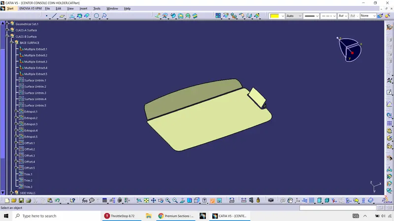
3. Next step is to un-trim the extracted surfaces using the "untrim" option.
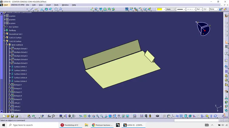
4. Select the group of surfaces and bifercate them based on the convenience. Next is to extrapolate the surfaces upto certain extent, where the CLASS-C can be passes trough it. Later it can be trimmed.
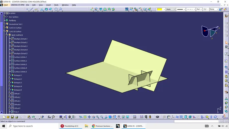
5.Next step is to offset the surfaces equal to the thickness of 2.5 mm and trim the Extrapolated surfaces and make it to attain the shape of the class A.
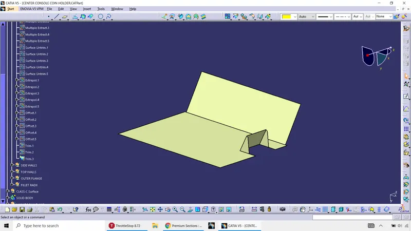
7. Next is to repeat all the above mentioned steps and form a single surface, without any fillet radius.
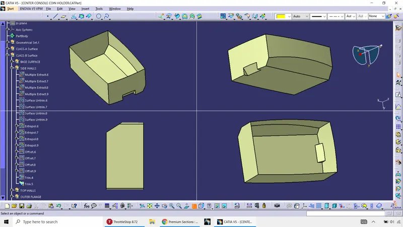
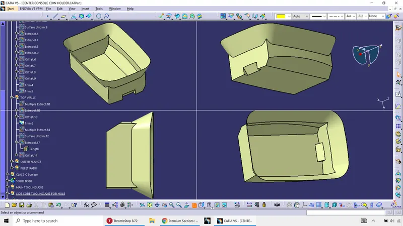
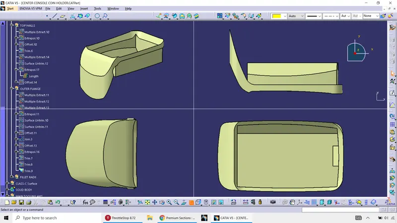
8. Next step is to create fillet radius for the surface. Care is to be taken while giving the fillet radius value such as
(R+T) for outer radii and (R-T) for inner radii.
R= Class A radii, T= Component thickness.
The final CLASS-B surface is being created as shown below.
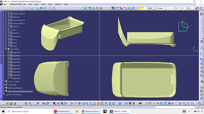
CLASS-C SURFACE: It is the surface created to connect CLASS-A and CLASS-B, so as to create a closed hollow surface.
STEPS TO CREATE CLASS-C SURFACE:
1. Extract the boundry of the CLASS-A surface.
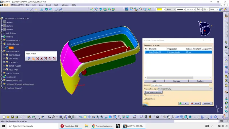
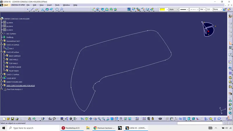
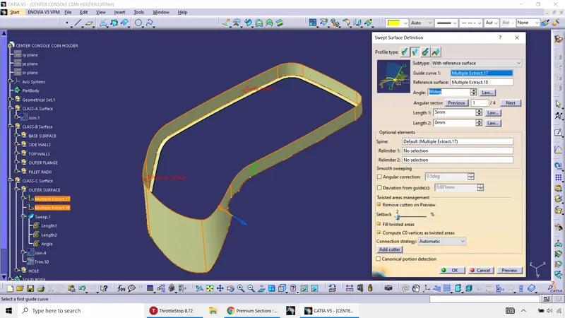
2. One out of two of the major techniques to create the Class-C surface is the Sweep command using "With reference surface". The refrence surface is extracted which are all the surfaces adjescent to the curve extracted.
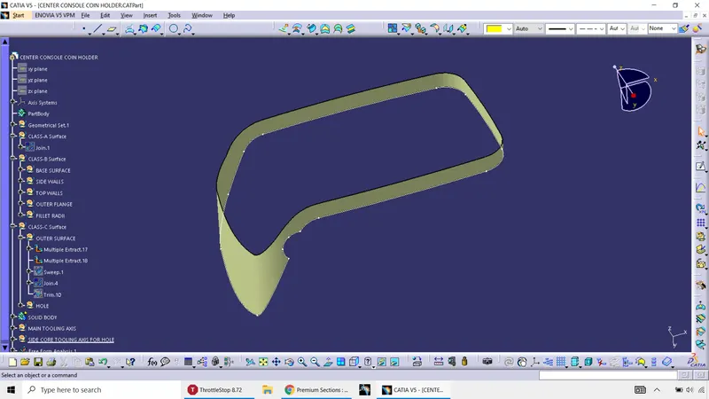
Then the sweep command is used for the curve and the surface present above.
The resultant of sweep is the Class-C surface as shown below.
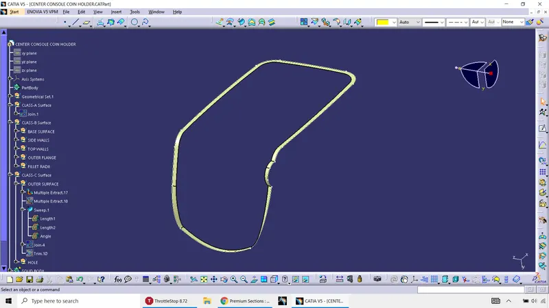
Same step is followed for the hole also
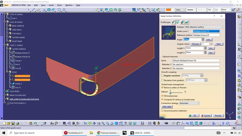
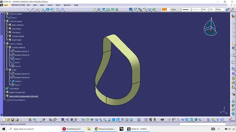
FINAL CLOSED SURFACE:
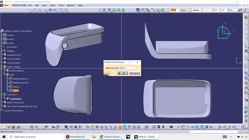
Initially the Class A and Class C needs to be joined using "Join" Command. Then the obtained result from joining Class A and C surfaces finally needs to be trimmed with the CLASS-B surface so as to obtain the below shown result.
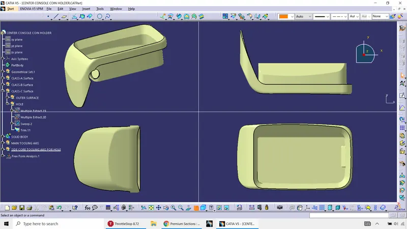
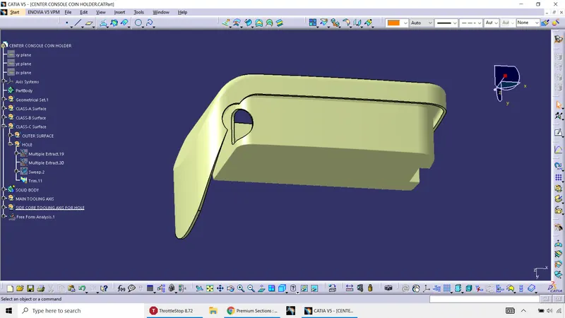
The above result now needs to be filled with material. Going to part design workbench, select on close surface option.
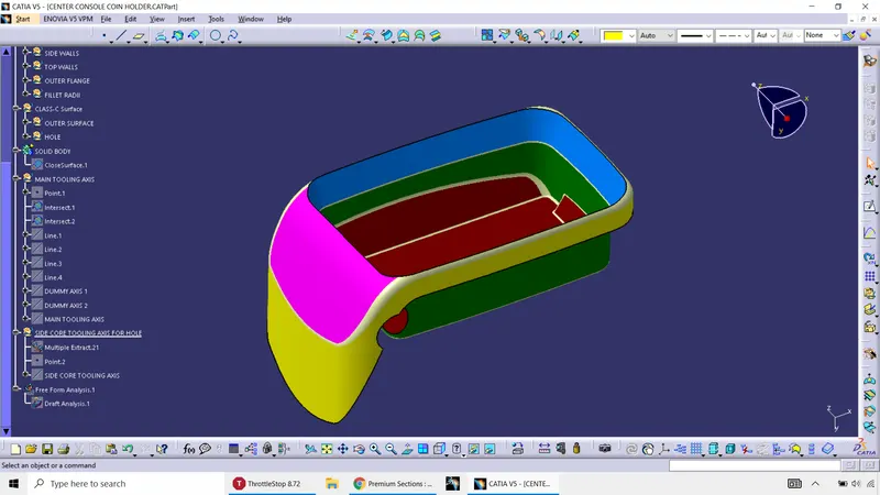
DRAFT ANALYSIS ON FINAL COMPONENT:
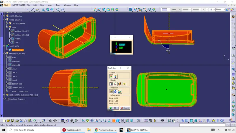
CONCLUSION: The final plastic component is being designed, analysed for Tooling but can be moved into manufacturing only if a certain minimum draft angle of 3 degrees is provided for the Class-A surface is ready to be manufactured in Injection Molding machine.