Week 8 - Challenge 4 - Bumper
Given Class-A surface
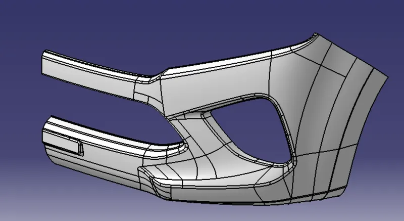
Draft Analysis Report for Class-A surface
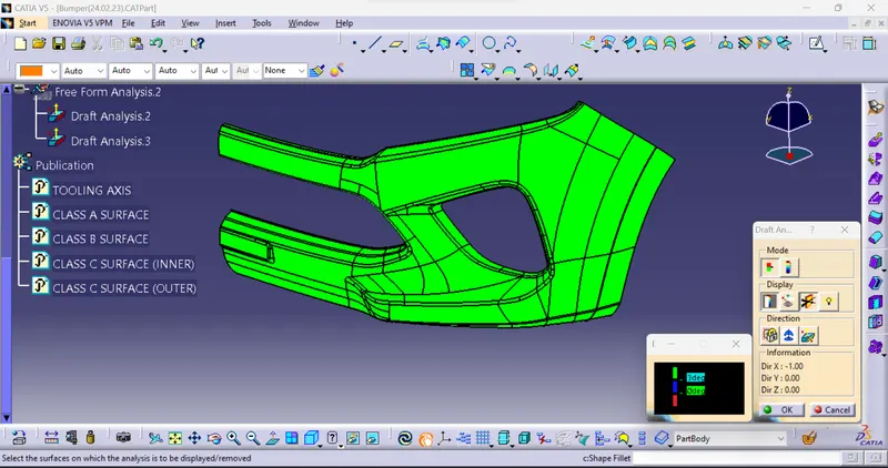
Draft Analysis Report for Coin Holder
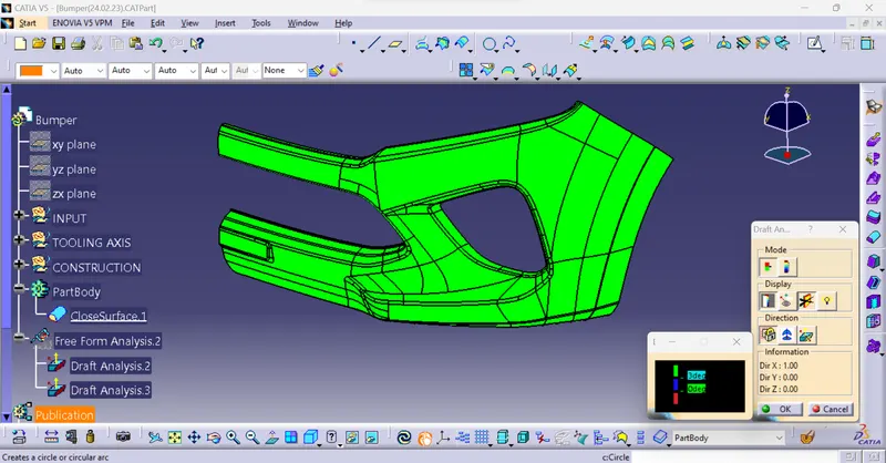
Coin Holder Solid model
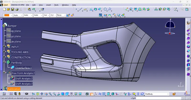
|
1. OBJECTIVE: Create the Bumper Plastic component through the given Class-A surface. To begin with, the tooling axis for the given Class-A Surface should be created meeting the requirements of the draft angle and at the end perform the Draft analysis on the model. With thickness of Plastic Part - 3 mm |
|
2. Definitions Class-A Surface: Class A surface is made from scanned data with different software like allias etc.. lass A surface having CURVATURE CONTINUITY Class-B Surface: Class-B surface having all features(Rib,boss,snap etc). It is created by extracting the all wall of the Class-A surface. Class-C Surface: Class-C Surface is used to joining the Class-A Surface & Class-B Surface. This surface is generated by sweeping the Class-A surface boundary. Draft Analysis The Draft Analysis allows the user to easily analyze a part for proper draft angle. A Draft Angle describes the amount of taper for molded or cast parts perpendicular to the parting line Tooling axis Tooling axis is tells about the in which direction core should be move. This tooling axis creating by Point and Direction . |
|
3. Procedure 3.1 Tooling axis making
3.2 Draft analysis for Class-A Surface.
Green for 3°, Blue For 0° Red for Below 0° 3.3 Creating Class-B Surface
3.4 Creating Class-C surface
3.5 Joining the Class-A, B & C surfaces
3.6 Solid model creation.
3.7 Draft analysis for solid model.
Green for 3°, Blue For 0° Red for Below 0° |
|
4. Result Initially Tooling axis was created by point and direction method. And the draft analysis is applied for class-A surface. After that Created the bumper Plastic component through the given Class-A surface with 3mm thickness. Now draft analysis is applied for plastic component of bumper and draft direction was found satisfactory. |