Week 8 - Challenge 4 - Bumper
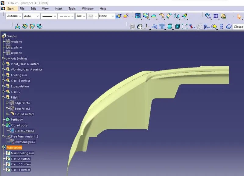
Create the Bumper Plastic component through the given Class-A surface. To begin with, the tooling axis for the given Class-A Surface should be created meeting the requirements of the draft angle and at the end perform the Draft analysis on the model.
Take the Thickness of the component to be 3 mm
Given Class A Surface:
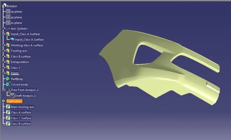
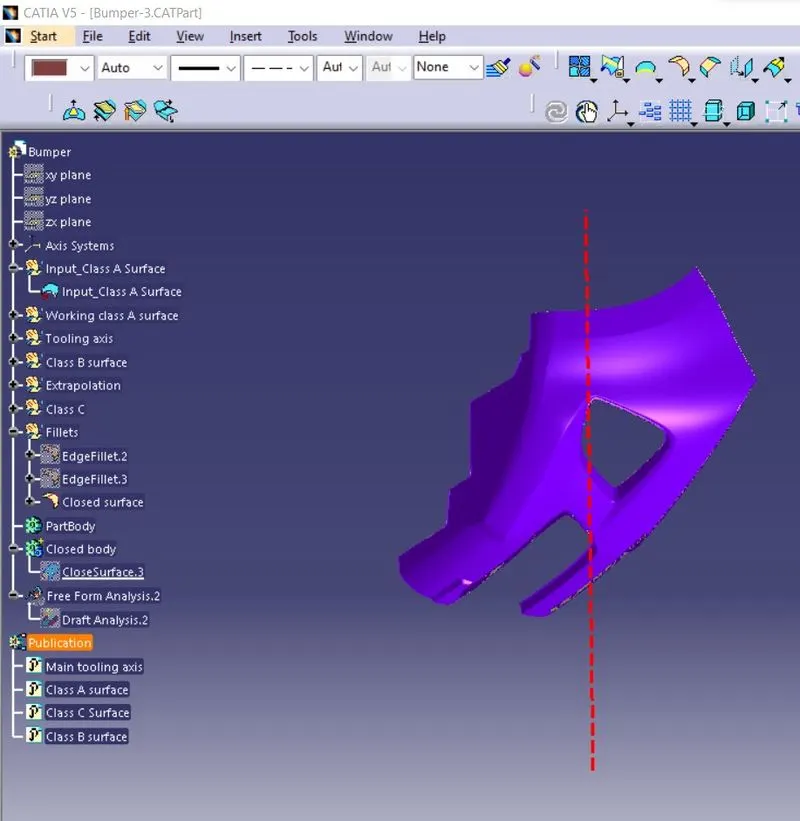
Tree structure
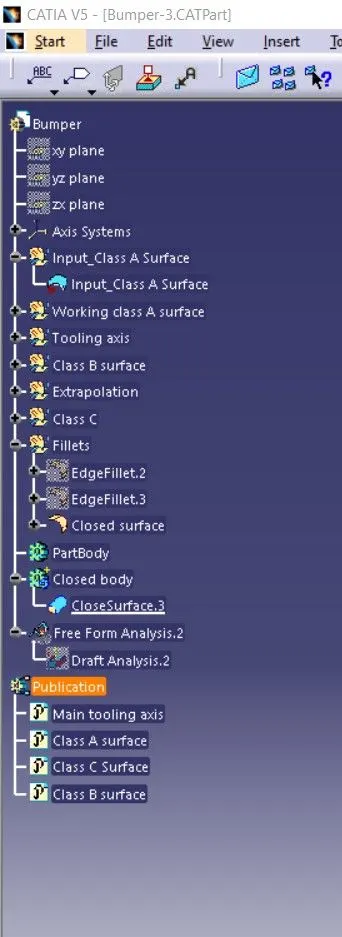
- Before proceeed make sure there is no gaps in between the given Class A surface,visually we can check it or by clicking boundary command.
- Find the best possible tooling axis of the component. The tooling axis is the line which the mould or cavity opens.
- Look for the best possible tooling axis according to the product shape
- Check all three axis, Along Y and Z, it is not faesible.so X direction is the best possible direction for tooling axis.
Creating a Tooling axis
Fig 1
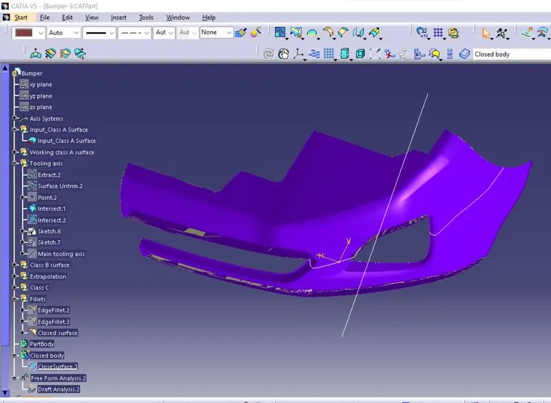
Fig 2
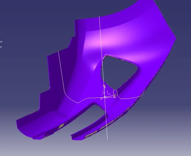
Fig 3
Create a point in the middle of the base and make a line through Z axis,this is our Dummy tooling axis,then create a intersect line through the point we created in the middle of the point, then help of point and sides of intersecting line create a Bisecting line as in fig 1.
Repeat the process in Y direction also,then create an intersecting line with both line,the new line in X direction will be the Main Toolng axis.(Fig 3)
Draft analysis
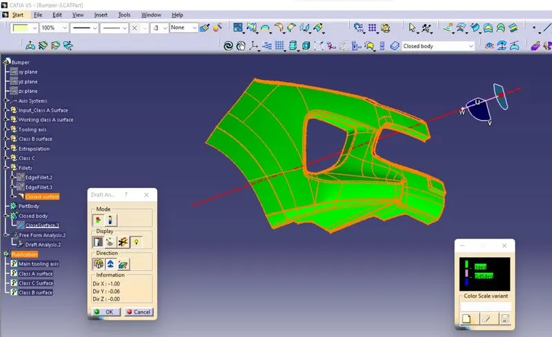
Now perform the Draft analysis using the Featured Draft Analysis tool in the tools.
Then after opening the draft analysis tool box ,go for the compass and place the compass alinged to tooling axis, and click on the lock symbol to lock the position. after alinging click on the surface which we want to do draft analysis,minimum draft angle given is 3 degree.it shows green colour once its finished.
Creating Class B Surface:
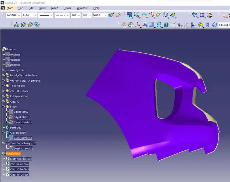
Before creating B surface,make an extract copy of given Class A surface,do an offset of Class A surface by using offset tool at a distance of 3mm ,after offseting some of the offseted surfaces may have missing surafces,that we need to work on it,using the join option for removing the discontinued surfaces and create new surfaces by using extrapolation tool,do the necessary trims.
Then trim the extra surfaces to get required surface.
Now apply fillet to required areas,consider to add thikness value to all fillets.
Class C Surface
class C surface is made by extruding edges of class A through class B surface by swept tool,the do the trimming option to remove unwanted surfaces.
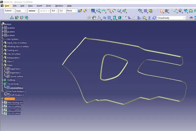
Closed Surface:
once class C is created join all the surfaces,we get closed surface,use boundary tool to check the part has any open profiles.
then open part workbench,apply closed surface tool on the final surface we have created to get the solid body
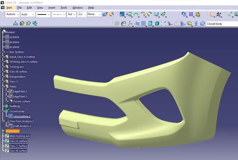
Solid body from closed surface
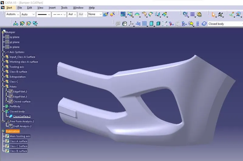
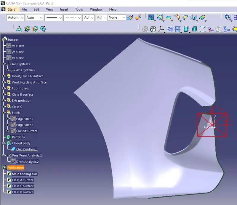
Isometric View
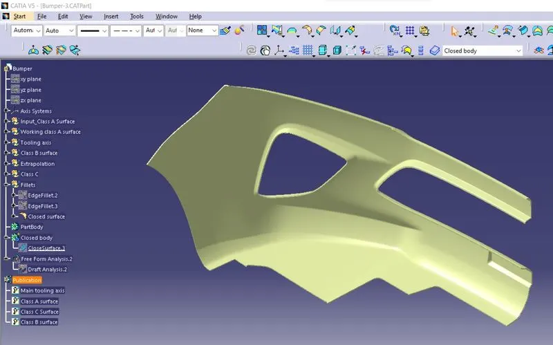
Front View
Side View
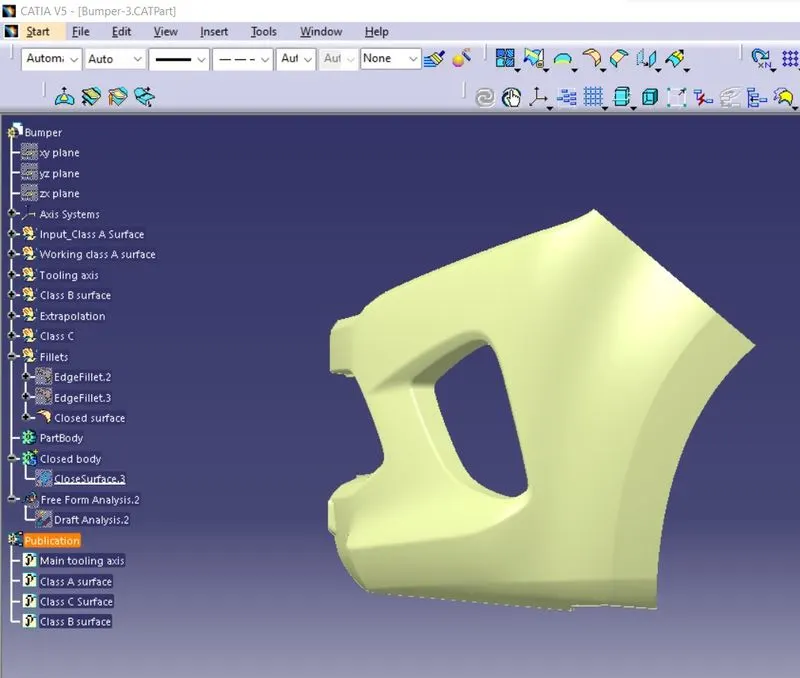
Top View