Week 8 - Challenge 4 - Bumper
Bumper tooling axis creation
TOOLING AXIS :
The direction in witch the mold or core and cavity opens is the tooling axis.
TOOLING DIRECTION:
The tooling direction is basically the direction thet the mold pulls apart . the mould is built in two separate pieces ,basically you have a cavity side and you have a core side . the core pulls apart from the cavity and thats the dyeline or the tooling direction .
CREATION OF TOOLING AXIS :
- first we need to check the model surfacess witch axis tooling axis is sutable.
- after selecting the axis (x , y, z , any one )extropolate the one surface
- after extripolating using point option to creat the one point on the center of the extrapolating surface .
after cerating the point using point and line option in line commant to create a 90degree line along the creating point. TOOLING AXIS CREATION IN BUMBER MODEL
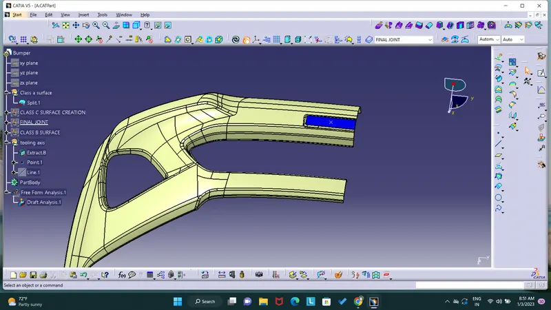
this is bumber model class a surface , the bluecoolor region or patch is my desided tooling axis creation using explorate command to explorate the region.
after compliting this process we need to create the tooling axis so we need to create a point on the this explorate surface
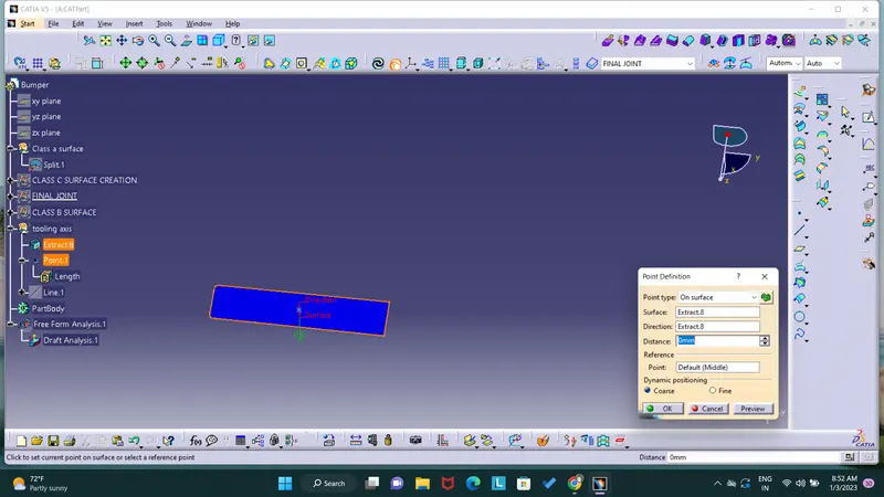
using point command , after creating point creating a line on the surface 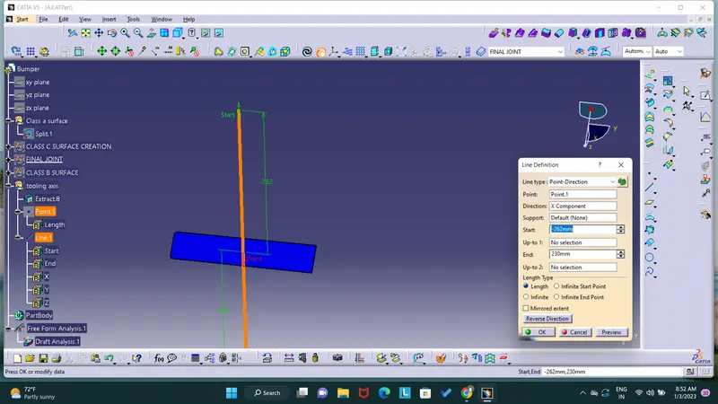
this is my tooling axis . we need to verify once the tooling axis is correct or not ,verifying picture is shown in below
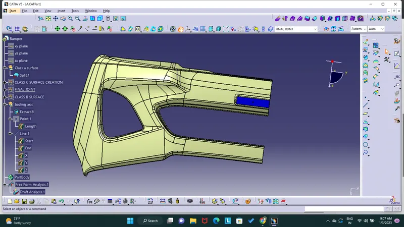
select the extraplotaing surface and click normal view mode the check wether the tooling axis is ok or not
DRAFT ANALYSIS
DRAFT ANALYSIS:
The draft analysis technique is used to analyze whether our part model created in cad is manufacturable based on the draft condition applied.here the part should get easily removed from the mold. no parts can be ejected ftom the tool if it is having a straight 90 degree profile from its base surface . a small draft angle is provided to each and every area of the component in order to get easy removel of the component from the tool.
creation of draft analysis:
step1:
change the view mode to customize view parameters and select the material option from the mesh.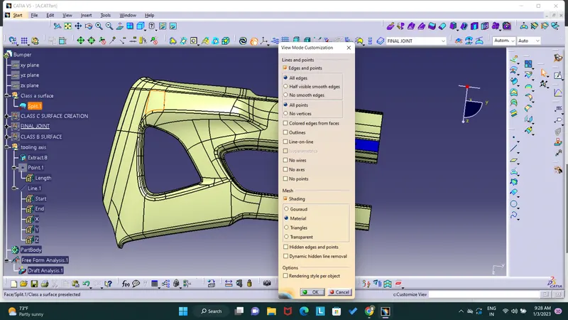
step2 ; select insert and go to analysis option and select the draft analysis tool
after selecting this tool i get a two windoes and pick the campass drag in to tooling axis fix properly aswellas and inverse draft driction tool and select the class a surface
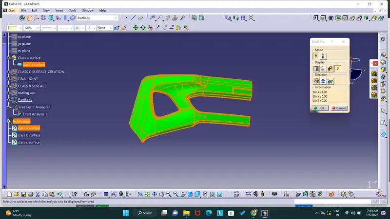
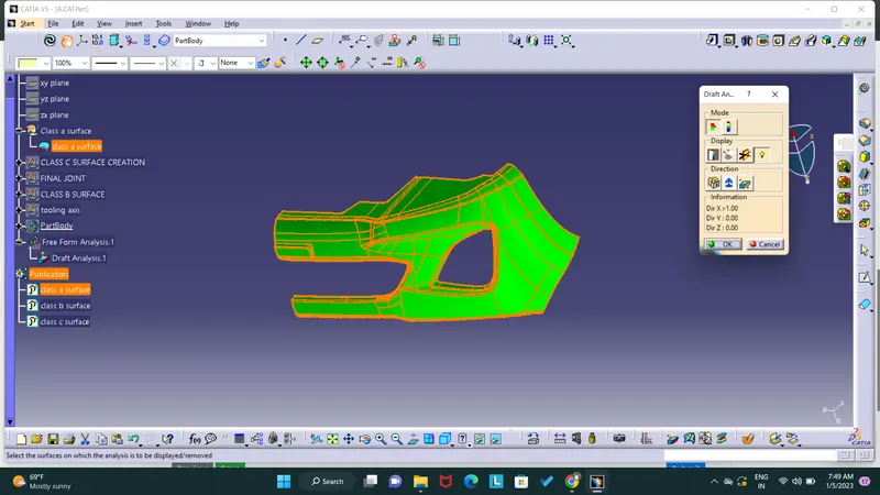
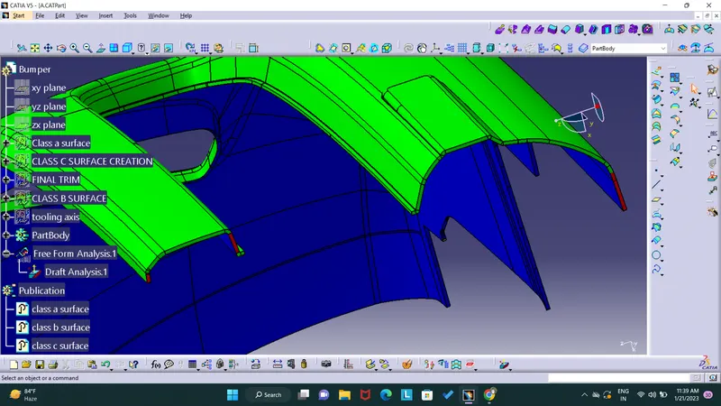
we need to check the class c surface draft angle : aswellas go to click and class c surface and create the draft analysis
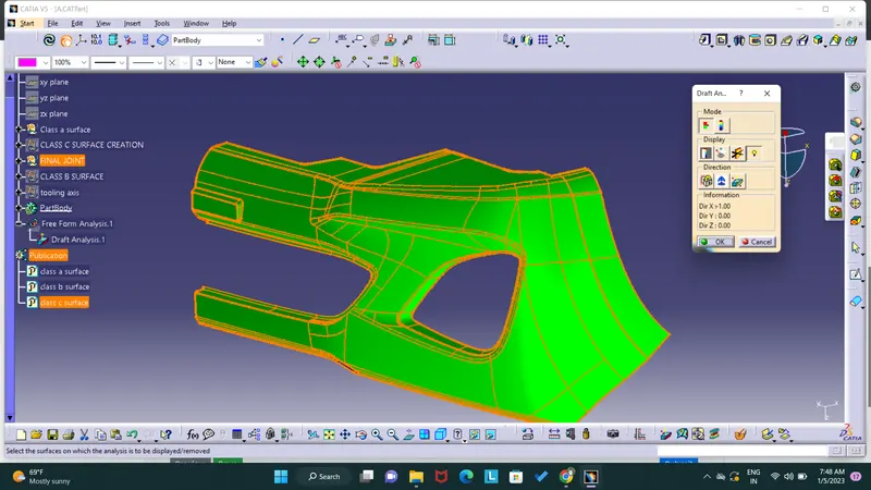
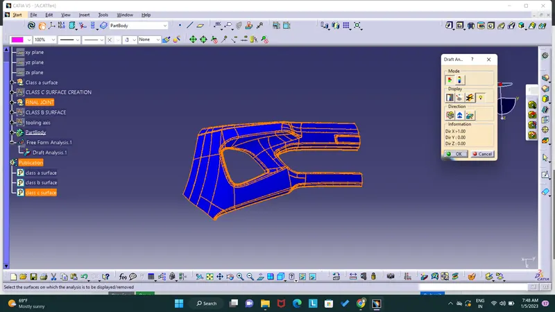
the surface is fully in blue and green colour so this draft angle is ok .
draft analysis report.
class a surface :
class c surface:
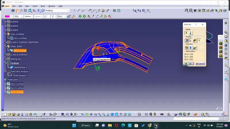
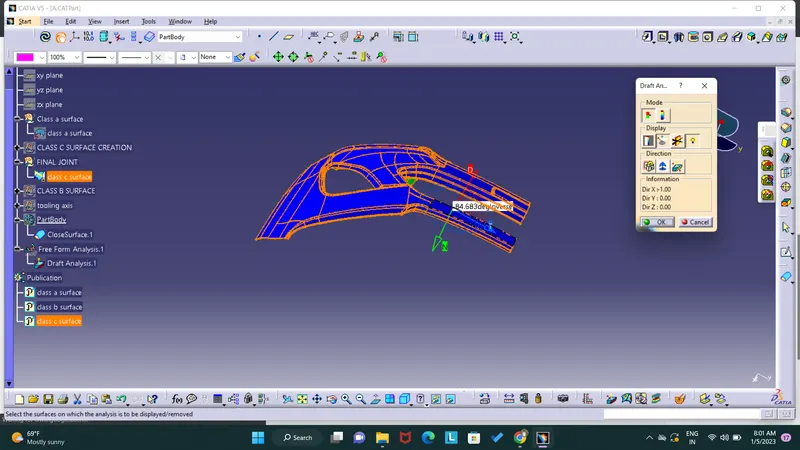
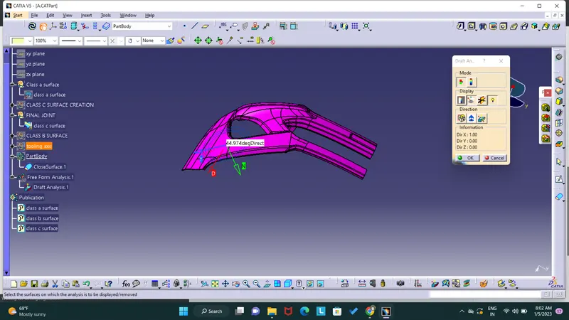
at the draft angle 3degree i get a draft errors, the errors are shown in below .
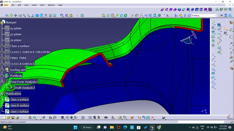
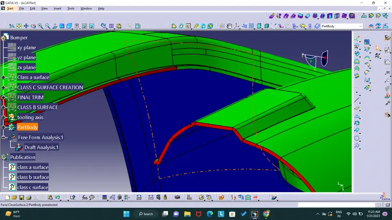
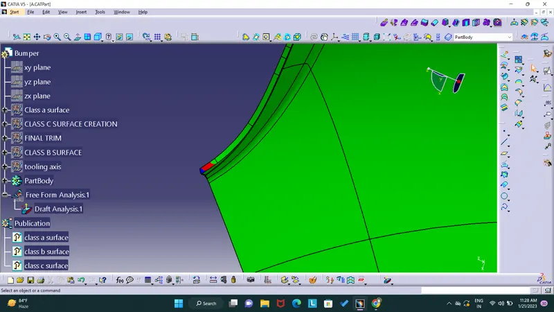
after reducing the draft angle up to 2.6 this amount of draft only clearing
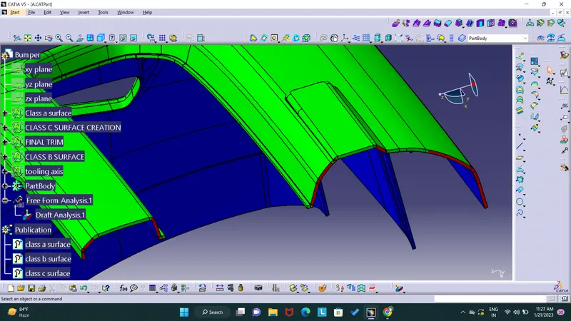
after reducing draft angle up to 1 degree small amount of draft angle only clear
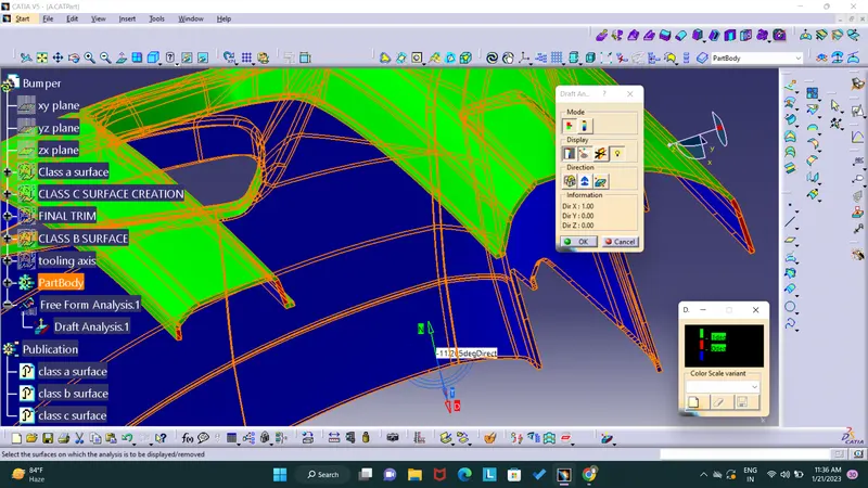
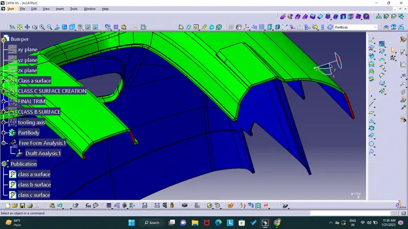
draft angle up to 0.5 still not clear