Week 8 - Challenge 4 - Bumper
CREATION OF BUMPER BODY FROM A-SURFACE
AIM :
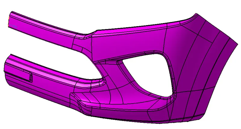
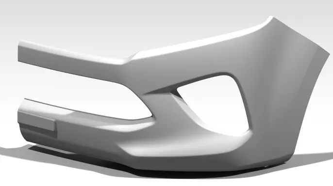
To create a body of Bumper from the input given which was the A-surface of a Bumper. The created body should be a closed solid volume which should be feasible for manufacturing and Tooling. The draft angle and draft analysis of the component should be done.
In model, proper tree structure to be maintained and publications of Tooling axis,A,B and C surfaces to be done.
INTRODUCTION
A bumper is a structure attached to or integrated with the front and rear ends of a motor vehicle, to absorb impact in a minor collision, ideally minimizing repair costs.
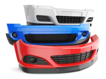
They are designed to absorb impact to the front and rear of vehicles and minimize low-speed collision damage. Today, standard passenger vehicle bumpers have a rigid reinforcing bar under the outer cover, with sections of compressible foam or plastic underneath.
A bumper is made up of four parts:
- Bumper cover.
- The bumper absorber.
- The bumper reinforcement bar.
- The bumper mounting system.
The first car bumpers were created all the way back in 1901 and consisted of metal beams attached to the front and rear of the car to protect it during a low-speed collision. Designed to protect the expensive and fragile components like the headlights, tail lights, hood, exhaust, and cooling systems, early metal bumpers were focused on sheer resilience.
Modern consumer production cars have almost completely switched over to plastic bumpers. Modern car bumpers are made from thermoplastic olefins, a blend of plastic molecules, rubber, and a reinforcing filler like carbon fiber or calcium carbonate. This blend of materials creates a scratch and impact-resistant plastic that can bond with a wide range of paints and finishes, making it ideal for vehicle bumpers.
Plastic is the preferred material for modern car bumpers for several reasons. First and foremost, plastic is much lighter and more aerodynamic than metal, which improves the car's fuel efficiency. Plastic is also easier to shape, which is useful during both the manufacturing and bumper repair process.
Bumpers of most modern automobiles have been made of a combination of polycarbonate (PC) and acrylonitrile butadiene styrene (ABS) called PC/ABS.
OBJECTIVE
- To design Bumper as per automotive industry Standard.
- Create tooling axis for the given CLASS-A surface.
- Create B Class and C Class surfaces
- Create final surface model and convert it into solid body using close surface command in the part design workbench.
- Perform draft analysis for both Class-A surface and Final part body.
INPUT GIVEN:
-
A-Surface
-
Thickness of component is 3.00mm
- Draft angle is 3 degrees.
CHECKING THE INPUT - A SURFACE:
The A-surface or the styling surface is first checked for any gaps and other issues in its surfaces. This Surface acts as the input surface so any correction to be done should be with approval from the styling team or done by them. A- perfect surface is the one when a boundary is created, the lines are only on the edges of a component and its holes or cutouts as shown below. (See Image 1)
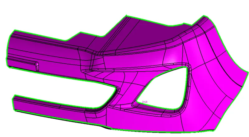
Image 1: A-Surface without any issues when created a boundary
CREATION OF TOOLING AXIS:
Tooling axis is the direction in which a core or cavity of mold opens. This Axis is very important to determine the orientation of the component in mold, core and cavity design.
The tooling axis is created by the inertia method by using the steps as follow
-
Click “Measure inertia” and select the A-surface
-
Click “Create geometry” in the Measure Inertia window.
-
In the Creation of Geometry window, select Non-associative geometry.
-
Click “Center of Gravity”
-
The Inertia point is created.( See Image 2)
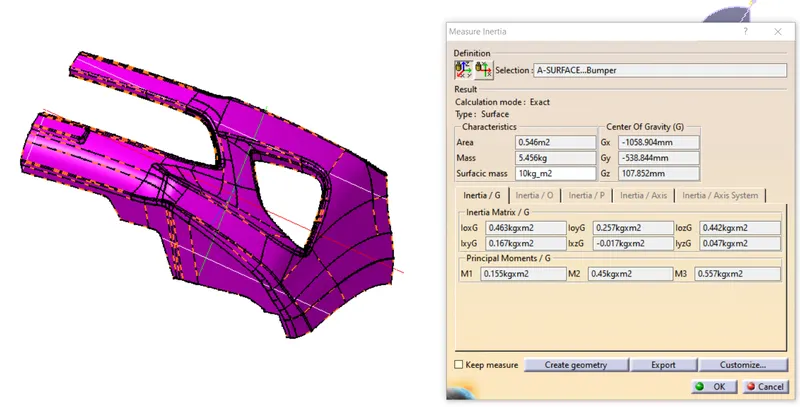
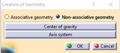
Image 2 : Creation of Inertia point
-
The component is viewed in all axes namely X,Y and Z.
-
It is determined that the X-axis will be the direction for the Tooling axis and a line is created Using the CG point and X-direction as direction of the line.
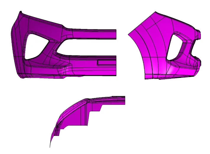
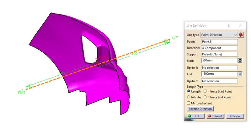
Image 2 : Creation of Tooling Axis
DRAFT ANALYSIS OF A SURFACE:
Draft analysis of the surface is carried to check if the surface or part can be manufactured with the required draft angle.
Draft angle is needed for the component to clear the core and cavity surface as it would have shrunk towards the center while cooling.
The draft angle in this design is 3 degrees. As A surface is a single surface there won't be much difference in color. The draft analysis of A-surface is shown below. (See Image 3 and 4)
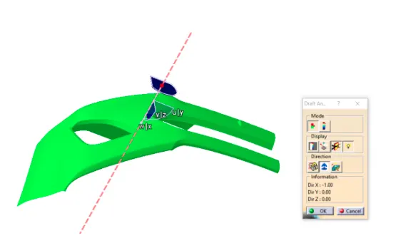
Image 3 : Draft analysis of A-surface
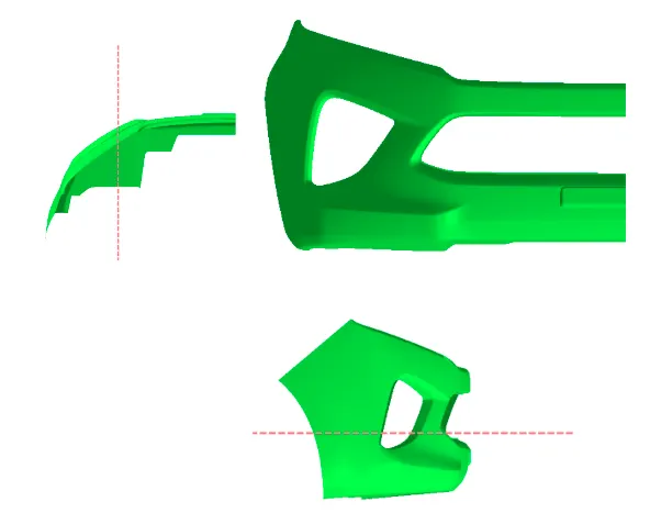
Image 4 : Draft analysis of A-surface , different views
CREATION OF B-SURFACE :
The A-surface is offsetted by 3.00mm as it is the thickness required.
The offset surface is the B-surface but had some issues like in some areas shown in below images.(See Image 5 and 6)
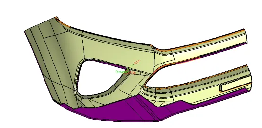
Image 5 : B-surface shown with issues.
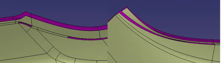
Image 6: Areas in B surfaces where offset was not done
The Areas where the B-surface has issues are corrected by closing them using commands like Multi section,Sweep,Offset and extract.
Finally all the created surfaces are trimmed or joined together with offset surfaces done earlier. This created a single single surface which will act as the final B-surface. (See Image 7)
B surface created is checked for any gaps or errors by creating a complete boundary as shown below.(See Image 8)
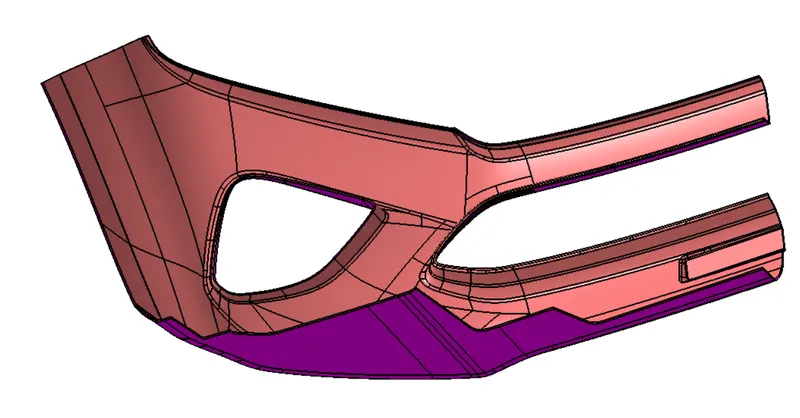
Image 7: A and B surfaces shown
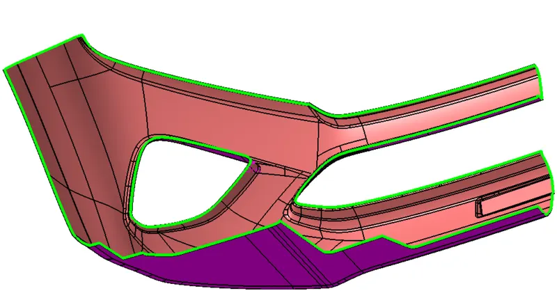
Image 8: Boundary of B-surfaces
CREATION OF C-SURFACE :
The A and B surfaces are connected by another single surface which is called the C surface. (See Image 9)
It is created by using sweep with A surface acting as the reference surface and curve created from the boundary of the same surface.
Sweep with draft direction is also used to create A-surfaces.
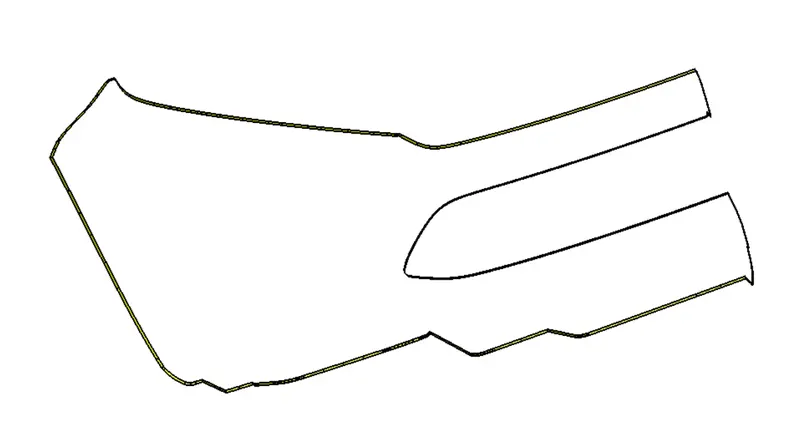
Image 9 : Creation of C surface
CREATION OF CLOSED BODY :
All the surfaces (A,B,C) are joined together to form a closed body.
Boundary is selected and the body is picked. Since an error popped up it can be understood that all surfaces are joined with each other to form a proper closed surface body.(See Image 10)
Finally in part design workbench, using close volume it is changed to a solid body.
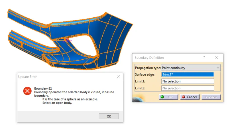
Image 10 and 11 : Checking the closed surface and the solid Bumper body
MODEL TREE:
The model tree created shows that all the geometrical sets are named for clarity.
The publications of Tooling axis, surfaces of A,B and C surfaces are done.(See Image 12)
Also the closed surface body and Volume is published.
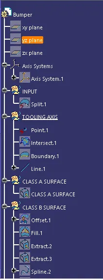
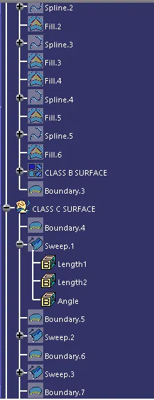
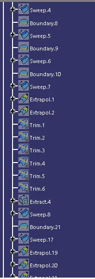
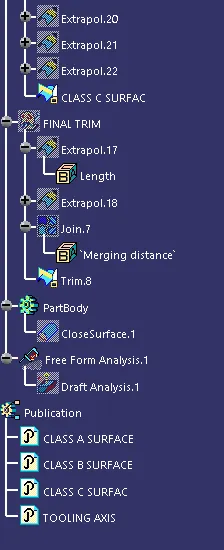
Image 12 : Model tree shown with geometrical sets and publications
DRAFT ANALYSIS OF PART BODY:
The final solid part body has to be analyzed using Draft analysis. This is done to check if all the areas of the body are satisfying the draft angle which is 3 degrees.
A draft angle is a taper applied to the vertical walls of the injection-molded component to assist with releasing the part from the mold.
Draft angles are a required feature of injection-molded custom parts. A functional part for injection molding has to have draft angles that face both the cavity and core sides. This will reduce the risk of damage to the parts and ensure that they can be ejected from the machine.
The Bumper body is checked using Analysis and images for it are shown below.
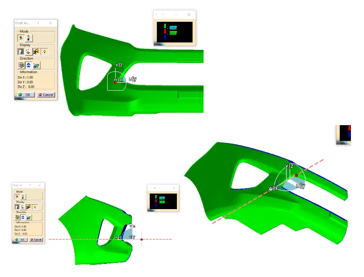
Image 13 : Draft analysis of the Bumper body
Conclusion:
The Draft analysis of the component showed that the component is feasible to be molded without any issues.
Thus it satisfies all design and manufacturing criterias needed for a proper part.
This concludes the report of Design of Bumper Body.