Week 8 - Challenge 4 - Bumper
The solid was created with a 2.5mm thickness as oppossed to the 3 mm in question. I assumed thickness and created it without observing the thickness value in question.Apologies.
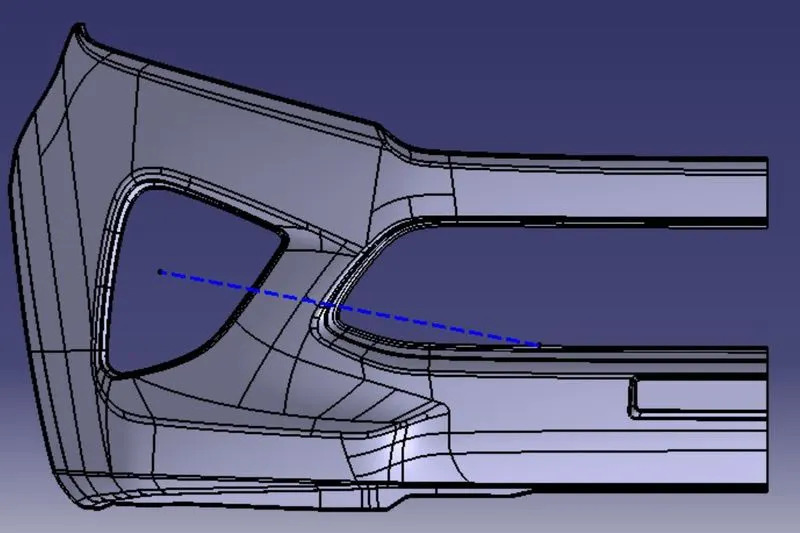
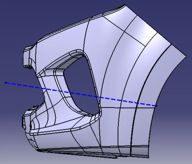
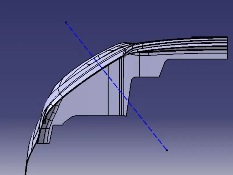
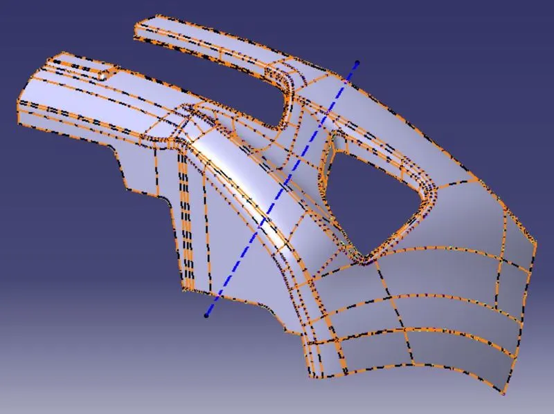
Screenshots of Bumper Solid part
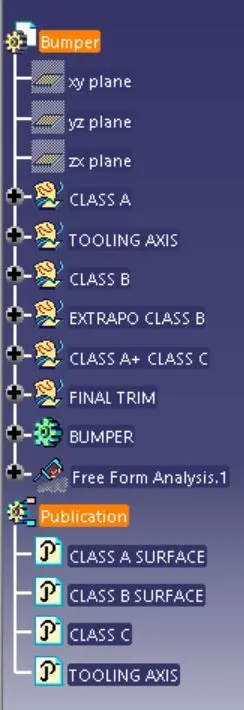
Report
Report on Tooling axis creation and its purpose
A tooling axis is an axis which passes through the body of the part created in the mould.It defines the direction in which the cavity and core move to clamp and clear the part to be created.It can be either the x , y or z axis directions.It is decide by the designer for easy clearance and cost effecctive ness in creation of the mold
In CATIA, we decide th tooling axis to be perpendicular to the flat surface ansd holes of a part as much as possible.Initially we create a dummy tooling axis.Later we check the different surfaces,fillets etc which are perpendicular to the tooling axis . To check any doubtful surface(if whether they can be ccleatred or not) we use the bisecting Method.In this method we select both the planes parallel to the tooling axis and create an intersect with the classA surface an the plane.Now we extend the lines of the surface which may be a hindrance.Later under Lines--->Bisection line--->select both lines---->select the line falling on dummy tooling axis(or next to it).This line becomes the original tooling axis
This above method is the Bisecting Line method for creation of the tooling axis.
Another way to create a tooling axis on complex Class A surfaces is by view the class A at different views and seeing from which view most number of planes are seen.Then select such a view and select a large plane on that view and draw a line normal to that surface passing through the class A.Now a majority of the surfaces on the part can be cleared by tooling axis alone.
Draft analysis
All surfaces of the solid parallel to the tolling axis can be cleared easily along tooling axis. Other unclear surfaces which are at an angle with the tooling axis need to be cleared by giving a draft. Here during creation of class C surface the sweep command is give along a curve with respect to the draft direction along the tooling axis. A minimal draft of 0.5 to 3 degrees is only required for proper clearance of solid.