Week 8 - Challenge 4 - Bumper
AIM
To create the bumper design plastic component through the given class-A surface.
OBJECTIVE
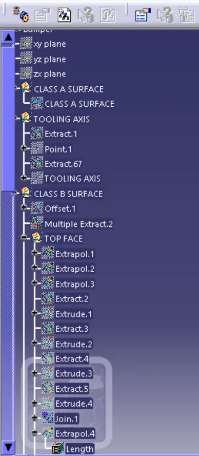
- To create a tooling direction.
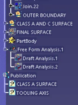
- To perform draft analysis for given A-surface and prepare the final close body.
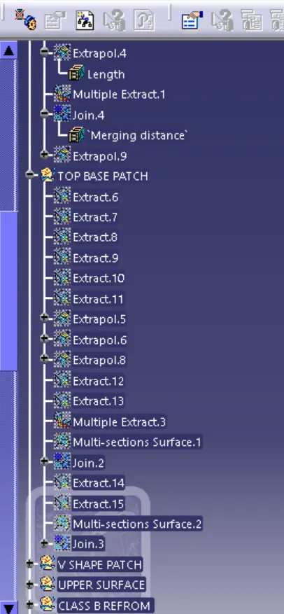
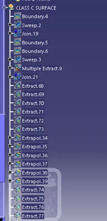
- To design the bumper plastic component by creating the B-surface and C-surface using the given class A-surface.
- Take the thickness of the component to be 3 mm.
INTRODUCTION
The input of the product designer is in the from of the A-class surface. The jop of the product designer is to creat the B and C surface keeping all the aspects for the mold.
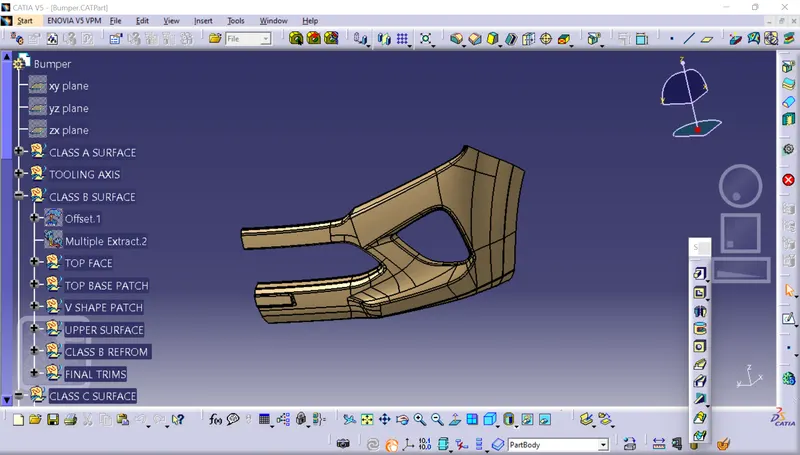
PROCEDURE
Tooling axis represent the opening and closing of the mold core and cavity during the manufacturing of the components. A plastic production to cutdown the cost of the component very less.
- Check the best tooling direction for the given surface.
- We can find out the best tooling direction by cross checking all the three axes.
- Here we can find out the best tooling direction for the pumper class A- surface is along X-axis direction.
- The mrthod 1 choose to creat the tooling axis is first extreacted a surface and create the tooling axis is first extracted a surface and create a midpoint on the surface.The introduced an axis system on that poind.
- Then creat a with the point and direction along X axis.
- Here both the outer flangers have 5.1-degree draft with respect of the axis creat. Hence going with the axis created will not make any difficulties during the draft analysis.
- Another methad is by creating intersection along Y direction.And then creat line on the wall and the creat a bisecting line with the lines on the wall and point created earlier we well ged an axis which well satisfy the draft analysis requirement.
DRAFT ANALYSIS
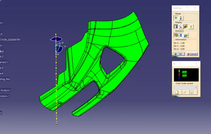
- The drafting analysis was performed on the class A-surface by using the feature draft analysis command.
- Using the command was set on the main tooling axis and the draft angle was changed to 3 degrees.
STEP