Week 8 - Challenge 4 - Bumper
AIM
Create the Bumper Plastic component through the given Class-A surface. To begin with, the tooling axis for the given Class-A Surface should be created meeting the requirements of the draft angle and at the end perform the Draft analysis on the model.
A detailed report should be done explaining the draft analysis and the tooling axis creation
Tooling axis creation
1) By observing part or component we have to choose direction of drafting. while doing this we have to consider geomety of component. All holes, fillets, chamfer etc have to take in our consideration and we have to choose direction of drafting.
2) now create a point on one of the vertex of a surface at on corner
3) create a line using point which is created on one of the vertex of the surface in X direction
4) thus tooling axis is created in the suitable direction meeting the requirements of the draft angle
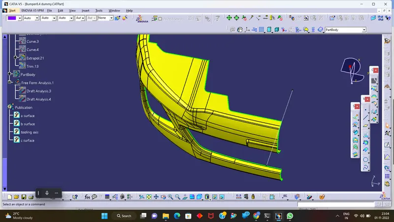
Draft analysis on Class A surface of Bumper
Step 1- Open draft analysis and move the compass to coincide with the Tooling axis as below.
Step 2- Lock the compass and check the radius/angles using the running analysis option
Step 3- Set the color code for the draft angle i.e green for above 3 degrees, Blue for 0-3 degrees, and red for angle value lesser than 0.
Step 4- Click on the surface using light effect, if the color goes green throughout means your draft analysis is good and ready for manufacture
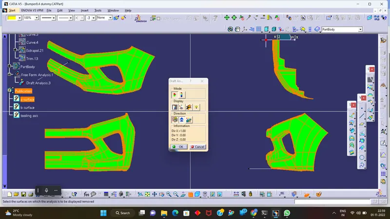
Draft analysis on final component of Bumper
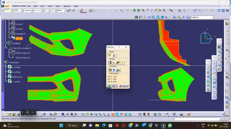
Tree Structure
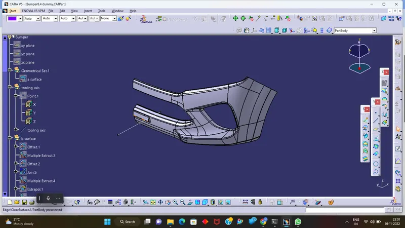
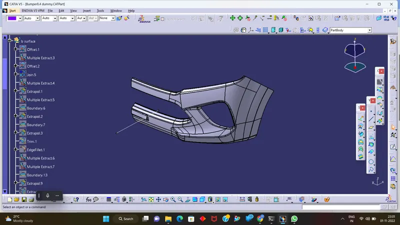
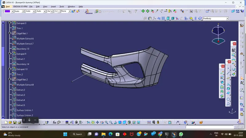
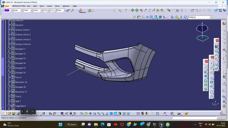
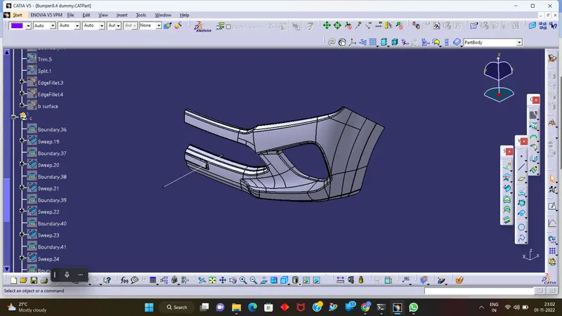
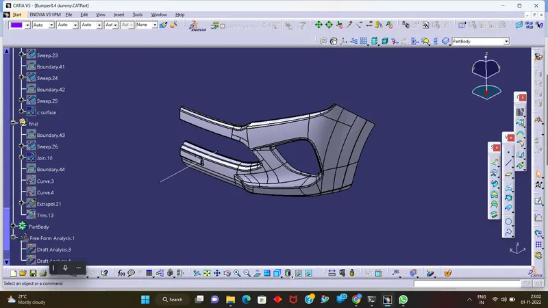
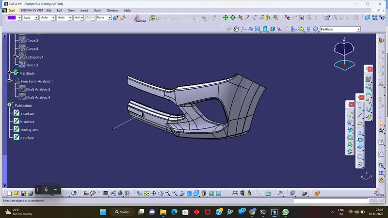
class B surface
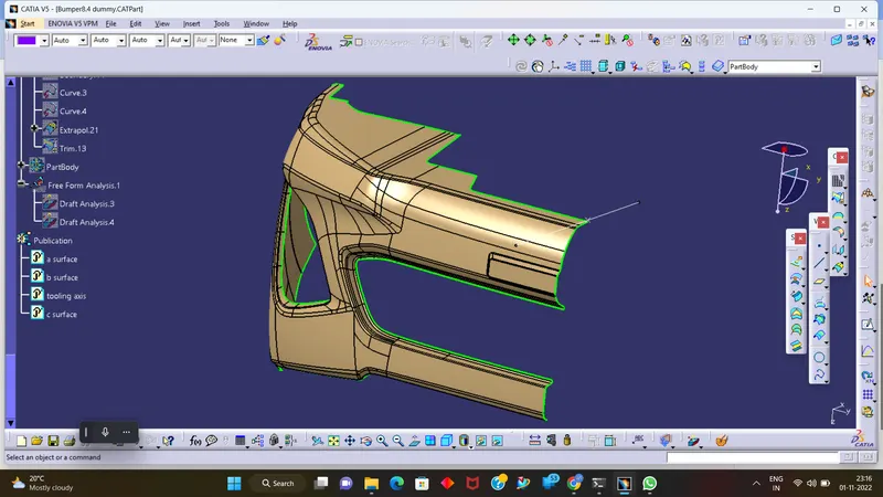
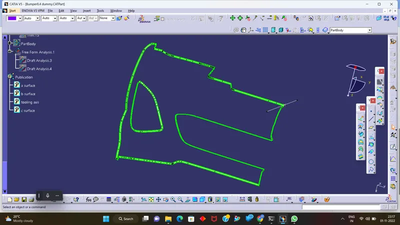
class c surface
Thank You.