Week 8 - Challenge 4 - Bumper
Your Answers
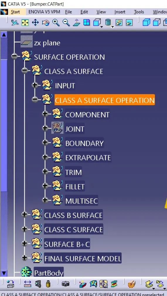
AIM: Design and analysis the draft angle by initiating the tooling axis reference given from the Class A surface Model then create class B and class C surface from the given Class A surface model.
Methodology
Tooling axis
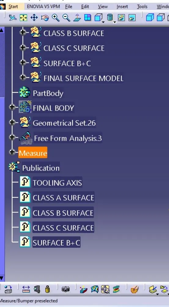
- Change the orientation to isometric.
- Check for the axis position and create of gravity point by using measure option, after creating a point create a reference line.
- Check for the draft analysis with resference to line and create a tooling axis
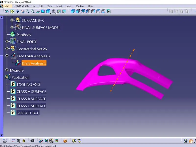
Draft Analysis
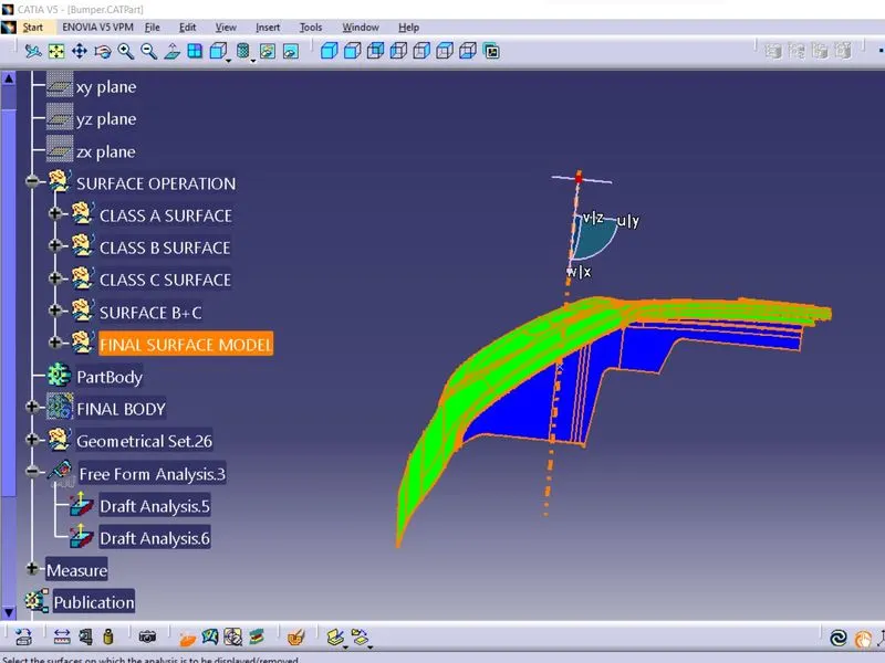
After creating a Tooling axis check for the draft angle on Class A surface with respect to the axis line by placing the compass on the axis line which is shown on the picture below, draft angle provided 3 degree (it can be varied as per the manufacturerS)
When the complete surface changes to green or any other defined color which is represented on the Draft analysis tab.
Designing Class B surface.
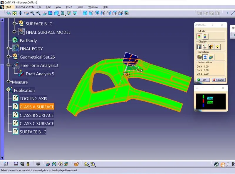
Designing a part that can be molded with a "straight pull" or "up & down" motion is a great way to keep the cost of the mold down. A straight pull mold is designed so that when the two halves (A side and B side) of the mold separate from each other, there is no plastic blocking the path of the metal in the direction of the pull. Undercuts on the part cause this blockage of path and require an action in the mold (cams, core pulls, etc.). Action in the mold can have a major impact on the cost (and overall size) of a mold.
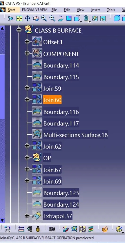
Offset the Class A surface model to 2.5 mm and extrapolate all the side edges of the surface model.
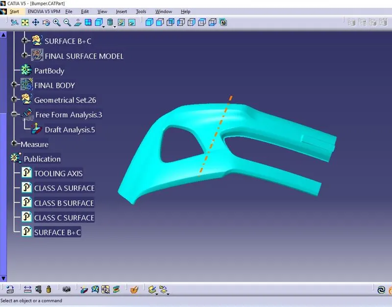
Uniform wall Thickness on Class C surface
Designing a part for plastic injection molding. Plastic shrinks as it cools which can lead to defects such as sink marks, voids, stresses, and warping. Plastic resin solidifies in the mold nearer to the outside of the part (closest to the mold surface). Thick sections of a part tend to pull inward, creating stresses, sink marks, or voids. Since thinner sections cool quicker, stress can build in the part between thinner and thicker sections, resulting in part warpage.
Draft angle allowance
Draft is required on all parts in the direction of mold movement in order to allow parts to release or eject from the mold properly. Draft is the angle in which the part is tapered to allow it to release. As the part cools, it tends to want to shrink to the core side of the mold. Adding draft helps the part to release. Most parts or applications require a minimum of 1/2 to 1 degree, however 11/2 to 3 degrees is widely accepted as the norm.
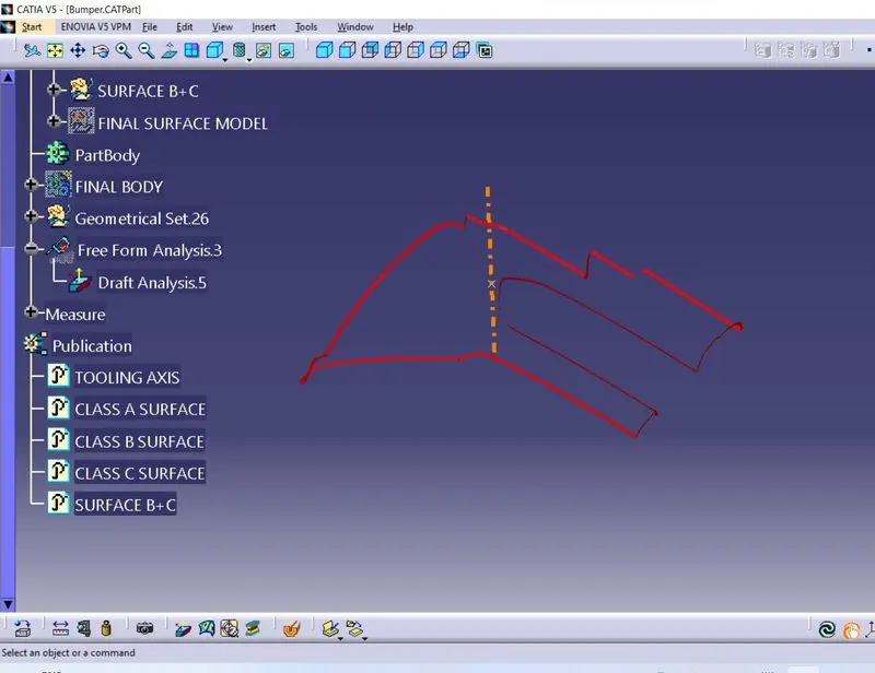
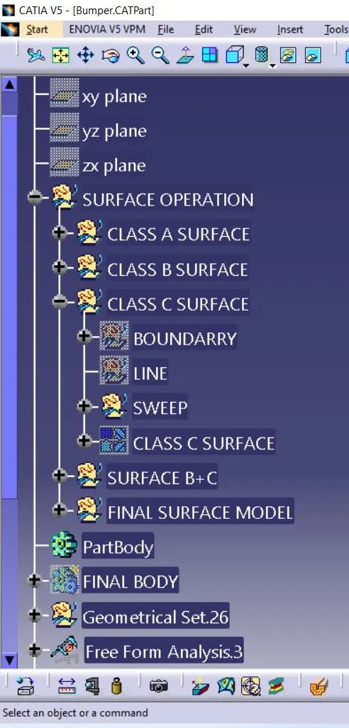
Using the Boundary command create a boundary and split the boundary line of the Class A surface depending on the profile of the surface model. And use the sweep command to extrude the surface over the Boundary lines at a draft angle of 3 degree and distance more then the thickness for boundary and 4 degree for the holes.
Trim Surface B and Surface c
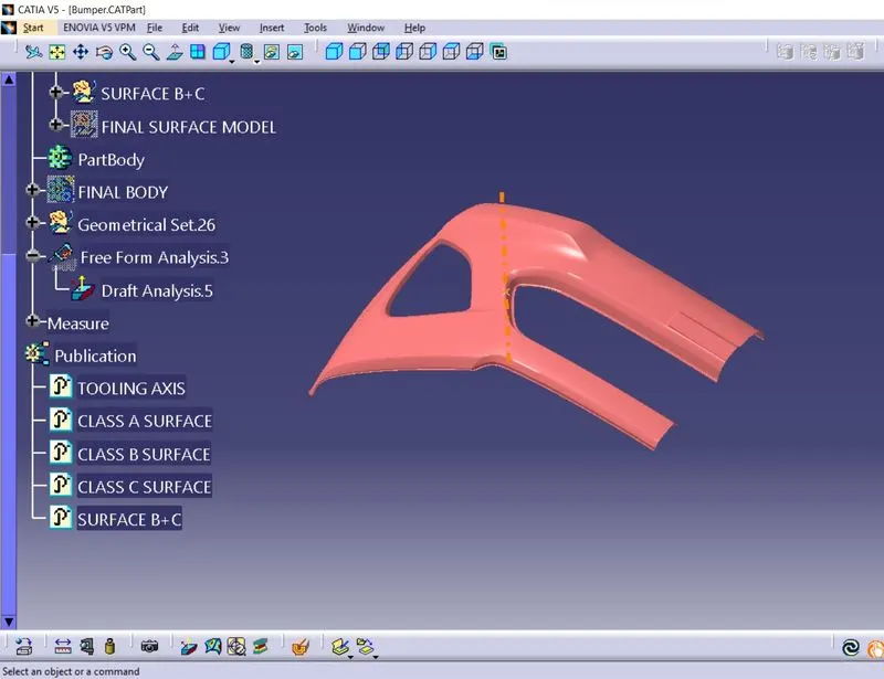
Join the Surface B+C and Surface A
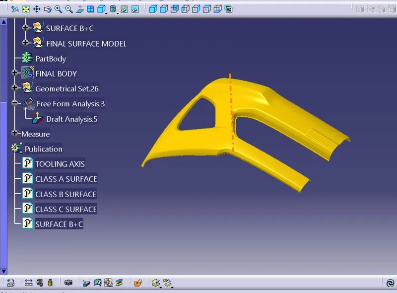
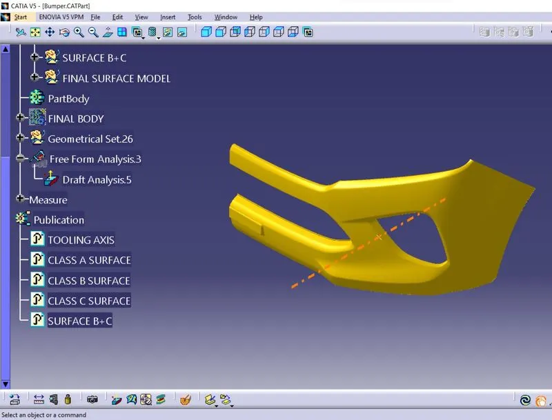
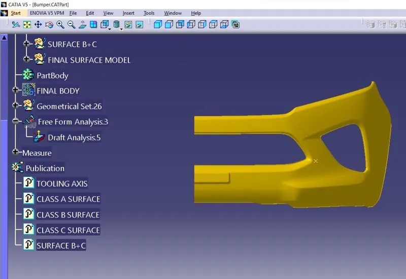
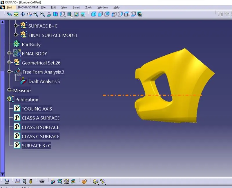
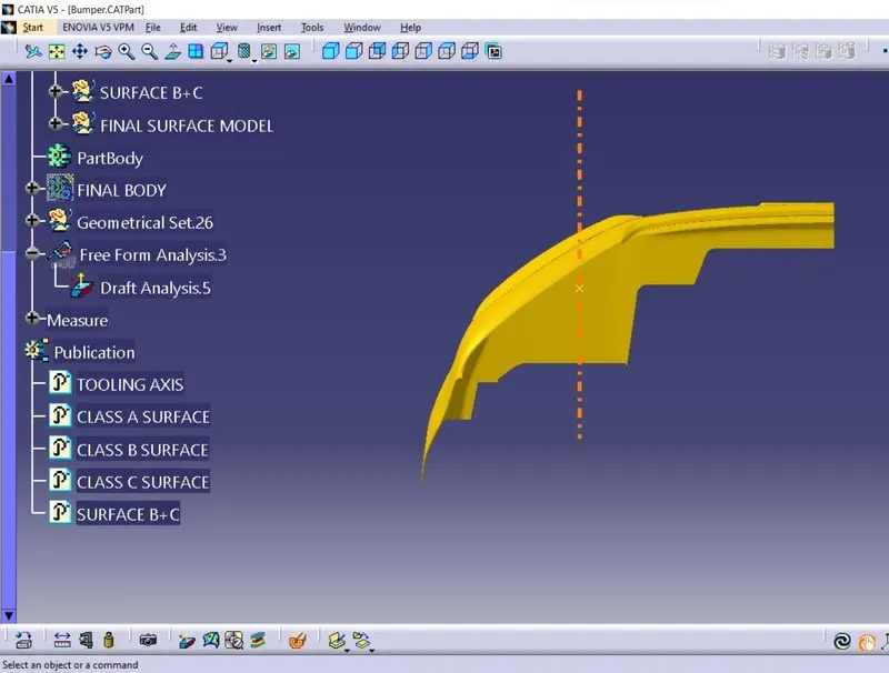
Use the close surface to create the complete model.
Analyse the draft for the final model for feasibility to design core and cavity.
This concludes greenary portion are core part nd blue portion are cavity part.