Week 8 - Challenge 4 - Bumper
Create the Bumper Plastic component through the given Class-A surface. To begin with, the tooling axis for the given Class-A Surface should be created meeting the requirements of the draft angle and at the end perform the Draft analysis on the model.
Take the Thickness of the component to be 3 mm
NOTE:
- Tree Structure
- Ensure Proper Tree Structure
- Geometrical sets should have a proper name based on the sketches present inside of it
- All the sketches should be created under the Geometrical set
- Use the Close Surface feature to make a solid body from the surface.
- Publications: Use the publication option and publish the below
- Tooling Axis
- Class A, B, and C surface
- Report
- A detailed report should be done explaining the draft analysis and the tooling axis creation.
- An explanation should be given on the way of creating the tooling axis, particularly the Bisecting method.
Here, we have given the class-a surface of the bumper and we have create the sold part from the class-a surface. For creating the solid part we need to create the tooling axis, draft analysis, class-b surface and classs c surface
Let look the class-a surface shown below
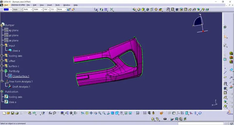
lets check the tooling axis for the given bumper class-a surface and create the tooling axis for the bumper
tooling axis is created on the flat surface, extracting the one flat face and creating the point on middle of the surface and make a line perpendicular to the surface and pass through the pont.
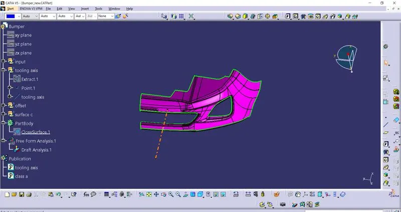
next, make draft analysis to the bumper with respective to the tooing axis.
now we have to perform thr angular draft analaysis for the class-a with the tooling axis weather class-a will clear the draft angle or not
for the draft analysis we will take draft analysis option from the insert tool bar and insert the geomentry on the tooling axis as shown below
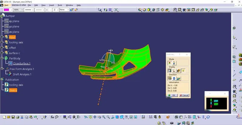
in area it is not clearing the draft analysis then we need to change the tooling axis
next we need to create the class-b surface , before create the b-surface we need to offset the class-a as the thickness is given is 3mm
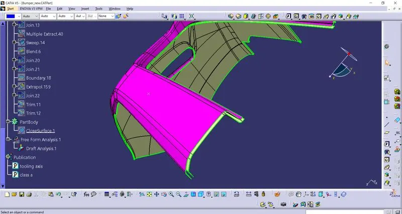
after offset the class-a surface at 3mm , then we got the class-b surface but with the small gaps in the surface now we have to close those gaps by using the different operations
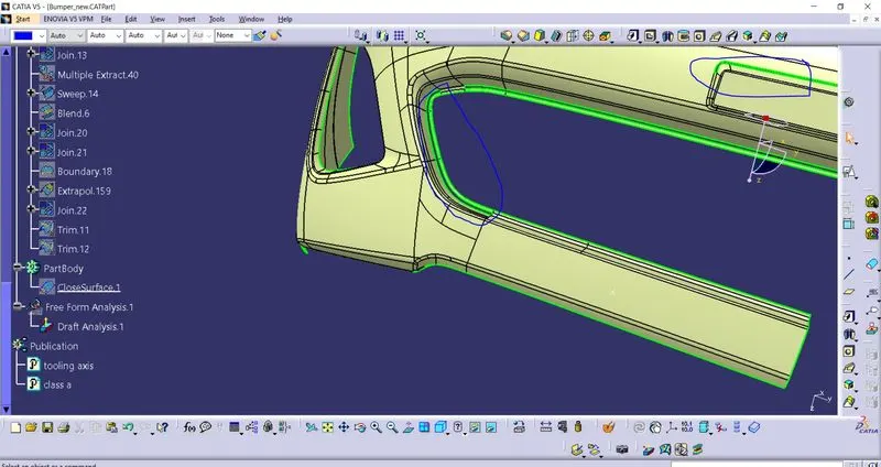
like as highlighted in the above pic we got some gaps now we have to fill the gaps by using different methods
surfacing filling-1
in this surface filling 1st we have too remove the exsiting radius to fill the complete radius, for removing the radius we have to etract the surface using the multiple extract like two faces as shown
multiple extract-1
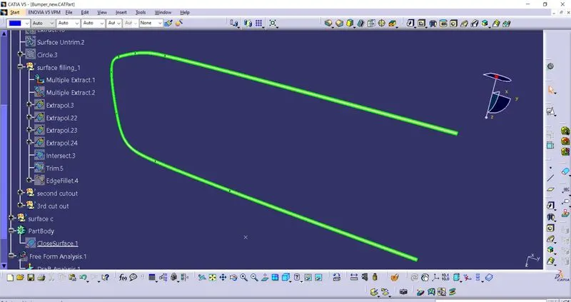
multiple extract -2
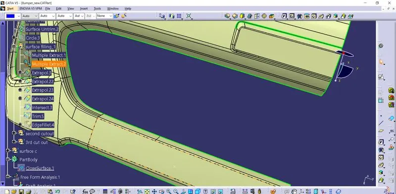
by using extraplote we will expand those required faces and trim the extra faces and applying the radius required
then the result will be shown below
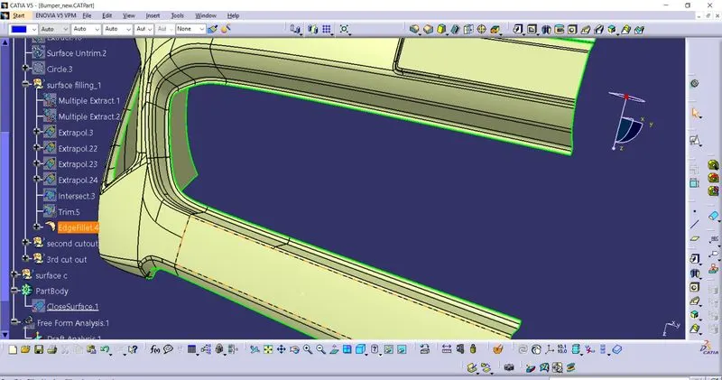
same like this we have to fill the remaning the two surface fillings
surface filling-2
in this surface filling 1st we have too remove the exsiting radius to fill the complete radius, for removing the radius we have to etract the surface using the multiple extract like two faces as shown
multiple extract-1
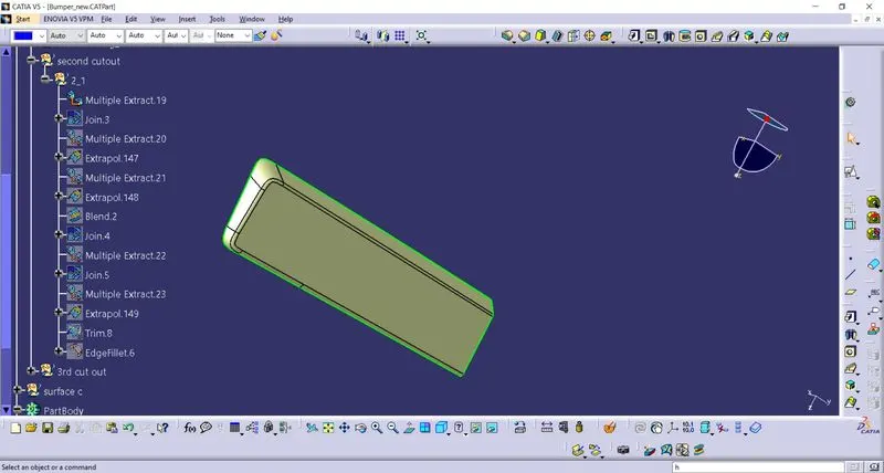
multiple extract -2
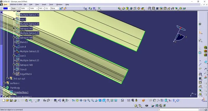
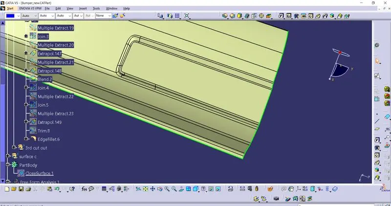
by using extraplote we will expand those required faces and trim the extra faces and applying the radius required
then the result will be shown below
surface filling-3
in this surface filling 1st we have too remove the exsiting radius to fill the complete radius, for removing the radius we have to etract the surface using the multiple extract like two faces as shown
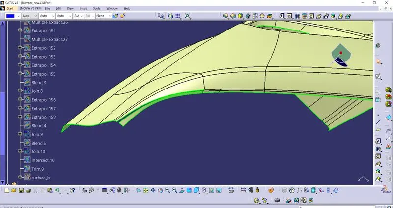
multiple extract-1
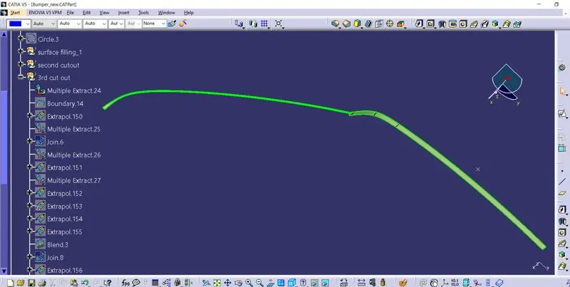
multiple extract-2
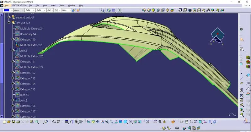
by using extraplote we will expand those required faces and trim the extra faces and applying the radius required
then the result will be shown below
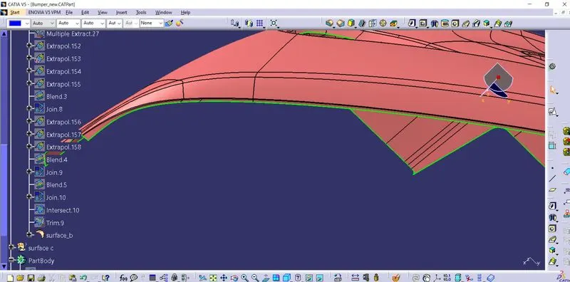
the above pic is the final surface-b
now we have to create the c-surface from the class-a surface by using the sweep command at 90 degrees from the class-a surface and join the class-a and class-c
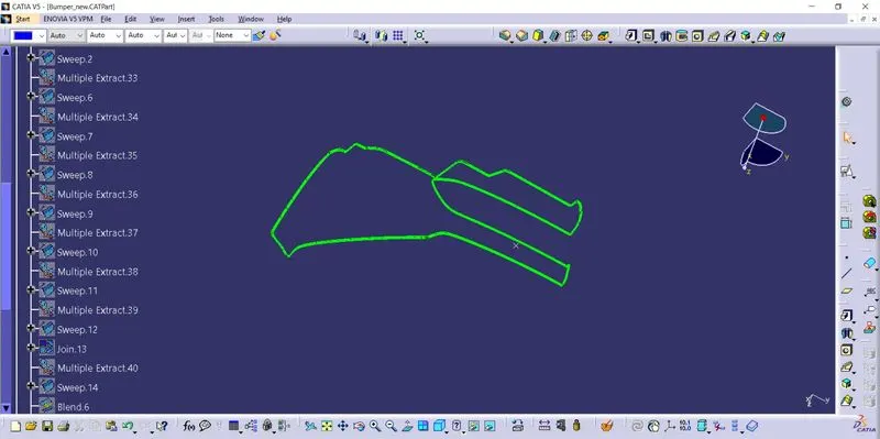
class-c surface
then trim the class-a+c surface with the class-b surface the closed surface will be formed the apply solid by using the closed surface command
closed surface
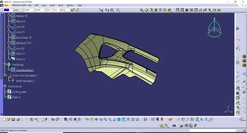
when the closed surface is done then then applying the closed surface command looks likes below
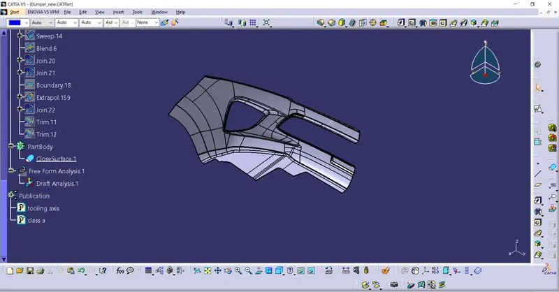
after sold body formed we have check on time with the draft angle analysis to verify the part
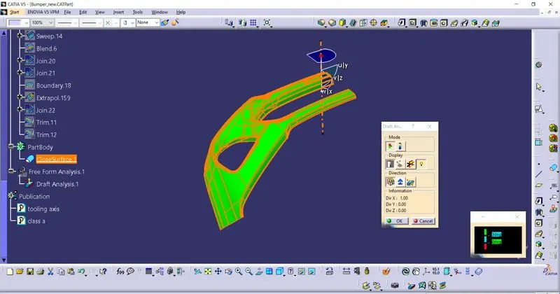
in the above image we can see the total surface is in green colour so that there will no issue with draft angle analysis