Week 8 - Challenge 4 - Bumper
Objective:
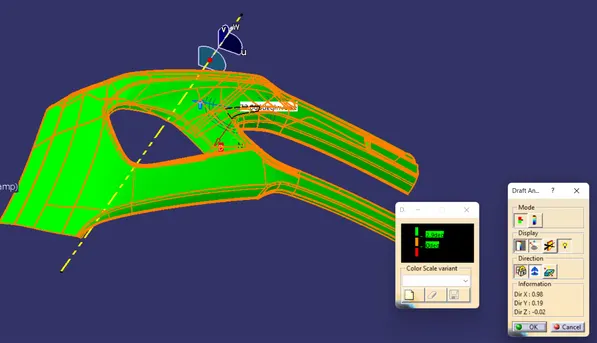
To create the Bumper Plastic component through the given Class-A surface. To begin with, the tooling axis for the given Class-A Surface should be created meeting the requirements of the draft angle and at the end perform the Draft analysis on the model.
Class A Surface:
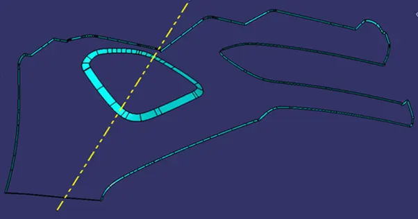
Class A surface was provided to us to design. The first step was to check the given surface for any gaps or irregularities. It was done by using boundary command. In this surface only two boundaries were found. I) Outer Boundary and ii) Headlamp Boundary. That means the surface is fine and ready to use.
Tooling Axis:
The direction in which a part is pulled out of a mould is known as the tooling direction. Basically, the mould is constructed out of two independent components. You have the Core side and the Cavity side. The Dye line or Tooling Direction is when the Core separates from the Cavity.
Steps to Create Tooling Axis:
- Visual Inspection on all the three axes.
- Creation of dummy tooling axis.
- Intersect the surface with respective plane.
- Extend two lines from the intersecting curves.
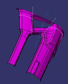
- Create a line bisecting these two lines.
- That is your tooling axis.
B Surface:
B Surface is created by extracting the A surface and off setting it for 3mm. This will give additional. Interior surface.
C Surface:
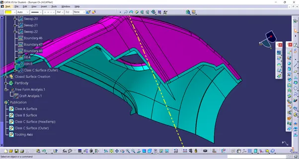
- It is the surface sed for Joiningg Class A surface with Class B surface.
- It is made by extracting the boundaries of Class A
- Then Use sweep command to extend it in tooling direction.
- After that trimming it with class B Surface.
Draft Analysis:
You can determine whether the part you drafted will be simple to remove using the Draft Analysis tool. In this kind of analysis, zones on the investigated element are identified by colour ranges where the deviation from the draught direction at any given place corresponds to predetermined values.
- Before going to Draft Analysis go to customized view parameter >under mesh >check material and then click ok.
- Now for draft analyses go to insert » analysis » feature draft analysis.
- Use the compasss to define the draft direction.
- In the colour scale change the draft angle to 3 or 2.9 degree.
- The component changes to green in indication of passing draft angle.
- Use running point to check the angle on the component.