Week 8 Challenge
Aim :
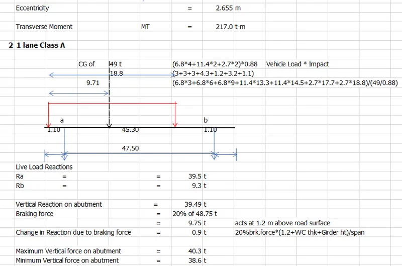
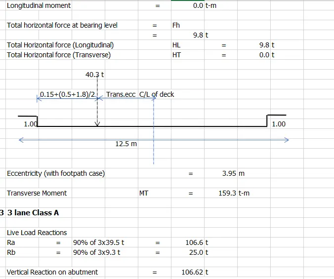
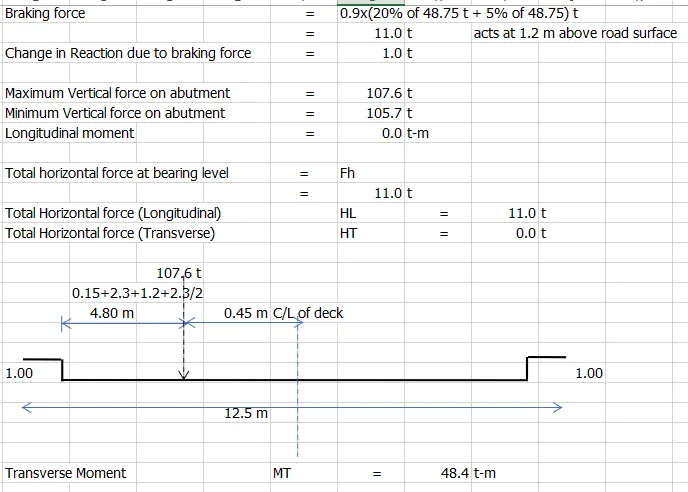
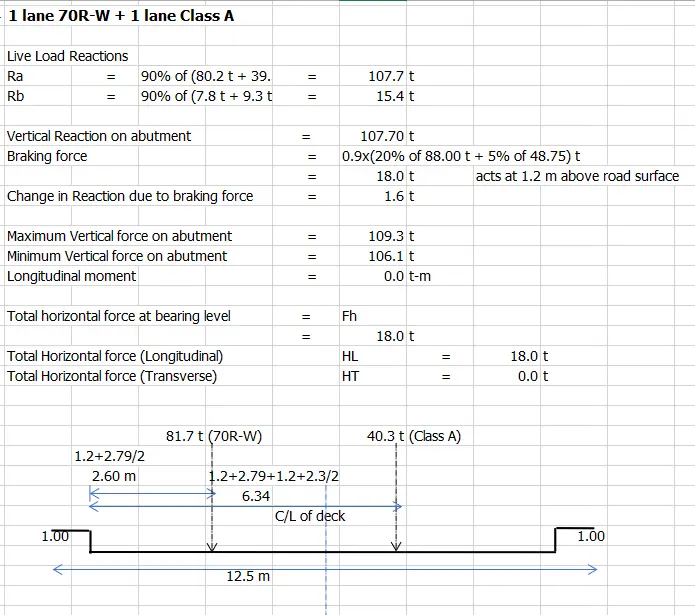
1) Calculate the loads as per IRC 6 assuming bridge in Bangalore on the pile group of the given bridge for the abutment.
2) List all the components of the well foundation and list the minimum kg/cumec(poundage) in them mentioning clauses from IRC codes and also list their functionality in respect to bridges loading.
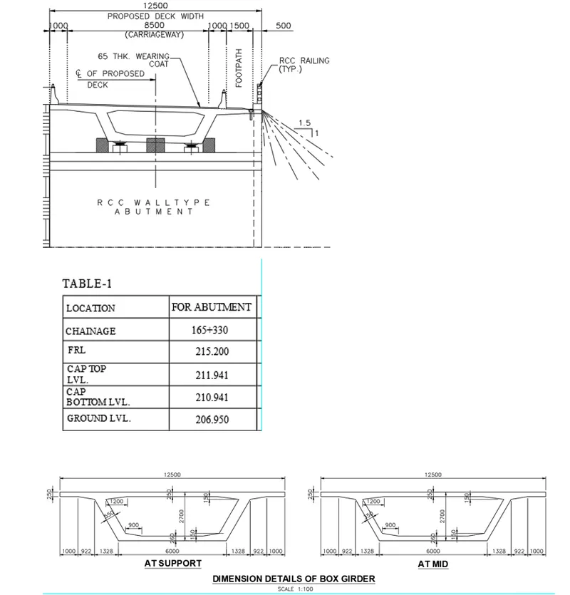
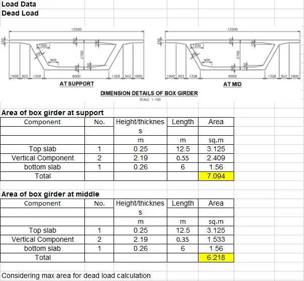
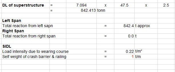
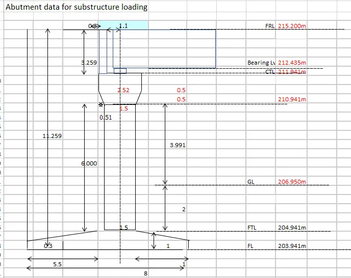
Introduction : The given PSC box girder bridge has a RCC wall type abutment. Span (c/c of expansion joint of the bridge) = 47.5m, c/c bearing distance= 45.3m. The bridge has a superstructure of deck width 12.5m, 65mm thick wearing coat. Given FRL = 215.2m , Cap top level = 211.941m, Cap bottom level = 210.941m & ground level of 206.95m. Weight of Crash barrier and railing can be assumed as 10kN/running meter. Ignore temperature and wind loading.
Procedure:
1) Calculate the loads as per IRC 6 assuming bridge in Bangalore on the pile group of the given bridge for the abutment.
Ans. Loads to be calculated for pile group as per IRC 6 are as follows:
| Loads | |
| 1 | Dead load (Due to self weight of superstructure, substructure, foundation and soil weight) |
| 2 | Superimposed Dead Load (SIDL) excluding wearing course due to crash barrier |
| 3 | Superimposed Dead Load (SIDL) due to wearing course |
| Now the bridge has 2 lanes in carriageway and a footpath. In future footpath can be removed and a For future three lane this bridge is designed for live load applicable for three lane. In that case SIDL mentioned above in 2,3 is ignored in design. | |
| 4 | Carriageway live load |
| i. 1 lane of 70R Wheeled | |
| ii. 1 lane of Class A | |
| iii. 3 lane of Class A | |
| iv. 1 lane of 70R Wheeled + 1 lane of Class A | |
| v. FPLL (ignored as future widening is considered) | |
| 5 | Seismic Load (ignored for this project) |
| 6 | Wind load (this can be ignored as per given data) |
| 7 | Temperature (this can be ignored as per given data) |
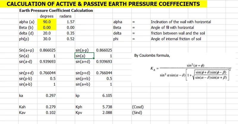
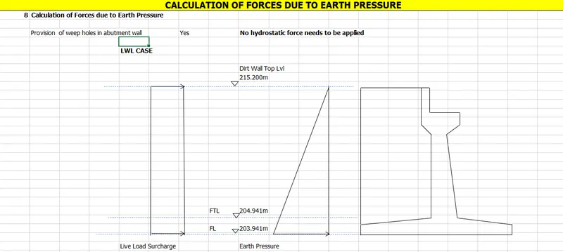
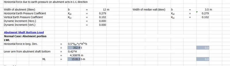
| 8 | Earth Pressure |
2) List all the components of the well foundation and list the minimum kg/cumec(poundage) in them mentioning clauses from IRC codes and also list their functionality in respect to bridges loading.
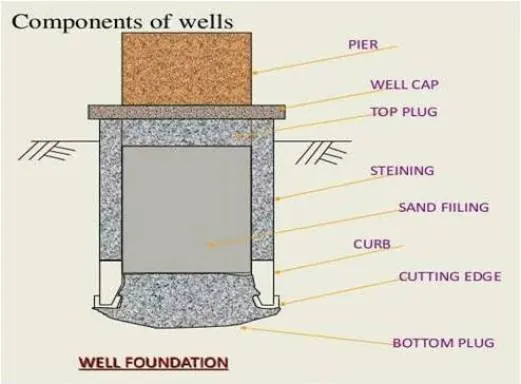
Ans. Components of well foundation are as follows:
- Well Cap
- Top plug
- Steining
- Bottom plug
- Well curb
- Cutting edge
- Filling inside (sand/water)
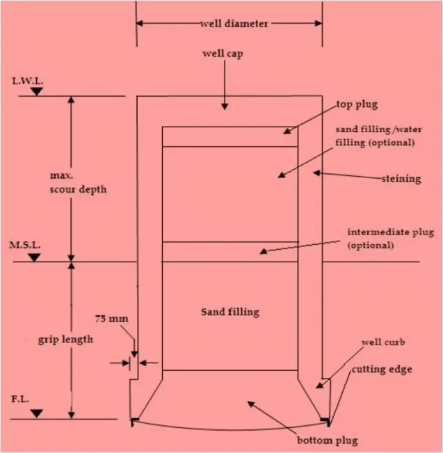
As per IRC 78 2014 Cl.708.3 & Appendix 3 reinforcement details for well foundations are as follows:
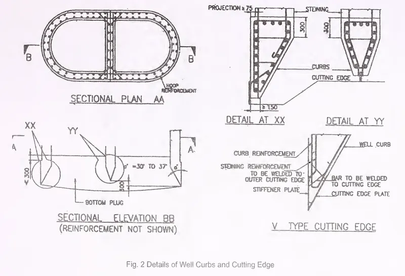
For plain concrete wells, vertical reinforcements (whether mild steel or deformed bars) in the steining shall not be less than 0.12 percent of gross sectional area of the actual thickness provided. This shall be equally distributed on both faces of the steining.
The vertical reinforcements shall be tied up with hoop steel not less than 0.04 percent of the volume per unit length of the steining, as shown below:
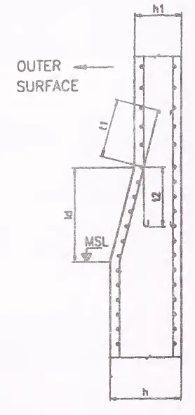
In case where the well steining is designed as a reinforced concrete element, it shall be considered as a column section subjected to combined axial load and bending. However, the amount of vertical reinforcement provided in the steining shall not be less than 0.2 percent (for either mild steel or deformed bars) of the actual gross sectional area of the steining. On the inner face, a minimum of 0.06 percent (of gross area) steel shall be provided. The transverse reinforcement in the steining shall be provided in accordance with the provisions for a column but in no case shall be less than 0.04 percent of the volume per unit length of the steining.
Functionality of well foundation components with respect to bridges loadings are as follows:
- WELL-CAP
It is a RCC slab laid at the top of the well steining to transmit the loads and moments from the pier to the well or wells below. Shape of well cap is same as that of well with a possible overhand of 150 mm all-around to accommodate lengthy piers. It is designed as a two-way slab with partial fixedity at supports. The top of the well cap is usually kept at the bed level in case of rivers with seasonal flow or at about the low water level in case of perennial rivers. Thickness of well cap is usually between 1500 mm to 2000 mm.
- STEINING
It is the main body of the well which transfers load to the base of the foundation. Steining is normally of reinforced concrete. Minimum grade of concrete used in steining is M20 with cement content not less than 310 kg/m3. To facilitate well sinking an off-set of 75 mm to 100 mm is provided in well steining at its junction with the well curb.
The thickness of well steining should not be less than 500 mm nor less than that given below.
t = KD*(L1/2)
Where,
t = minimum thickness of concrete steining, m,
D = external diameter of circular well or dumb bell shaped well or smaller plan dimension of twin D well, m,
L = depth of well in m below L.W.L. or top of well cap whichever is greater,
K = a constant depending on the nature of subsoil and steining material (taken as 0.30 for circular well and 0.039 for twin – D well for concrete steining in sandy strata and 10% more than the corresponding value in the case of clayey soil).
- WELL CURB
It is the wedge shaped RCC ring beam located at the lower portion of the well steining provided to facilitate sinking. Well curb carries cutting edge for the well and is made up of reinforced concrete using controlled concrete of grade M25. The cutting edge usually consists of a mild steel equal angle of side 150 mm. In case blasting in anticipated, the outer face of the well curb should be protected with 6 mm thick steel plate and the inner face should have 10 mm thick plate up to the top of the curb and 6 mm plate further up to a height of 3 m above the top of the curb.
- BOTTOM PLUG
After the well is sunk to the required depth, the base of the well is plugged with concrete. This is called the bottom plug. It acts like an inverted dome supported by the steining on all the sides and transmits the load to the subsoil and acts as a raft against soil pressure from below. Minimum grade of concrete used in bottom plug is M15. Thickness of bottom plug should not be less than the half of dredge-hole diameter nor less than the value calculated using following formula.
Where,
W = total bearing pressure at the base of well,
fc = flexural strength of concrete in bottom plug, , and,
ϑ = Poisson’s ratio for concrete, 0.18 to 0.20.
- TOP PLUG
The top plug is an unreinforced concrete plug, generally provided with a thickness of about 600 mm beneath the well cap to transmit the loads from the pier to the steining. Minimum grade of concrete used in top plug is M15.
The space inside the well between the bottom of the top plug and the top of bottom plug is usually filled with clean sand, so that the stability of the well against overturning is increased. While this practice is good in case of wells resting on sand or rock, the desirability of sand filling for wells resting on clayey strata is doubtful, as this increases the load on the foundation and may lead to greater settlement. In the latter case, the sand filling is done only for the part of well up to scour level, and remaining portion is left free.
- INTERMEDIATE PLUG
As discussed above, for wells resting on clayey strata, it is not preferable to fill the space inside the well completely with sand. In such cases, sand filling is not done or sand is filled up to the scour level. A concrete plug covering the filling is usually provided, known as intermediate plug. Usually, thickness of intermediate plug is taken as 500 mm.
Result:
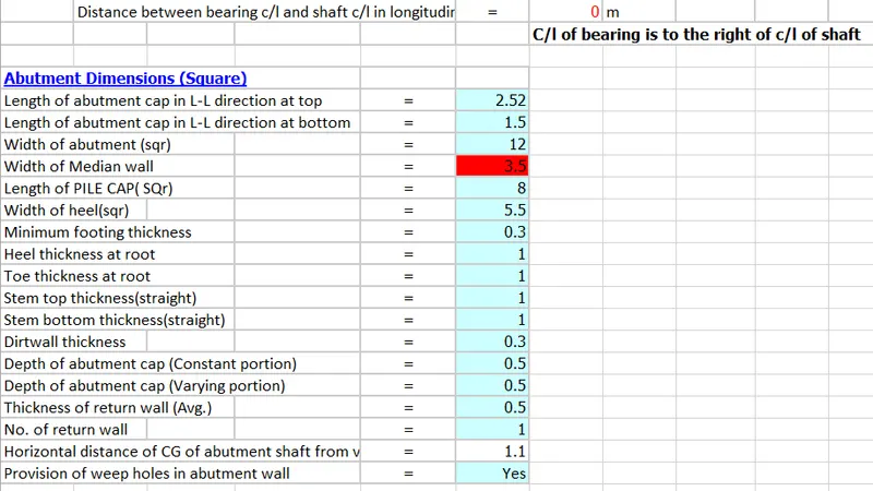
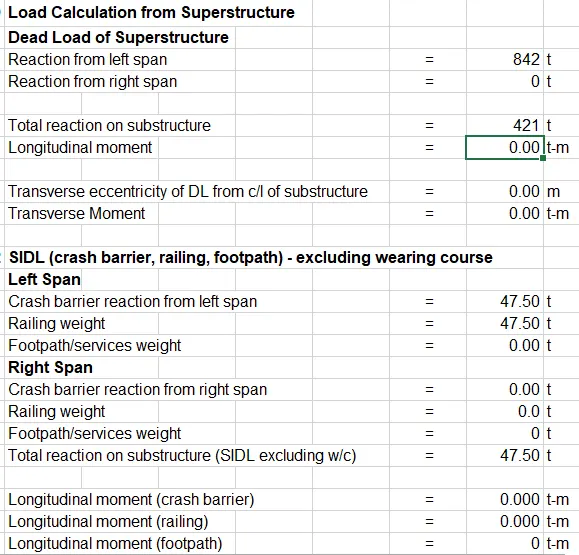
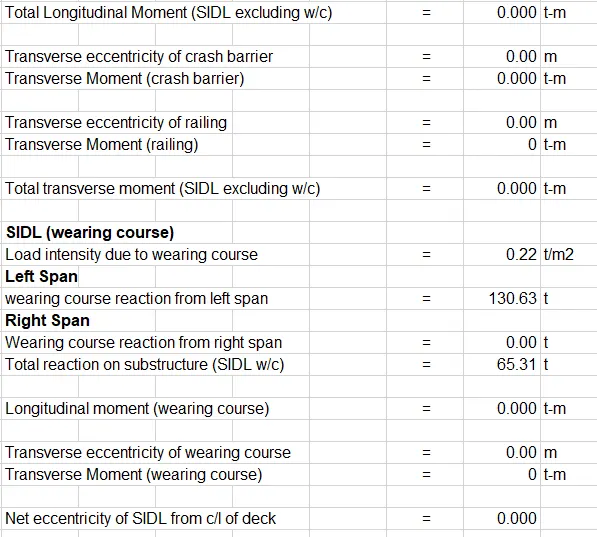
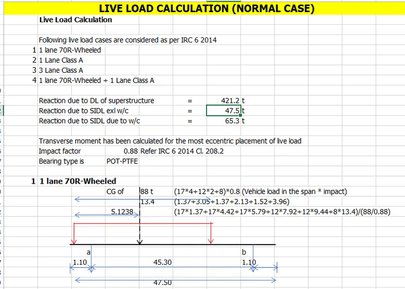
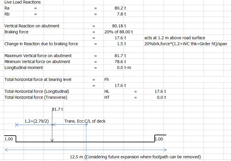
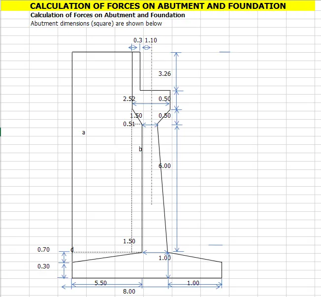
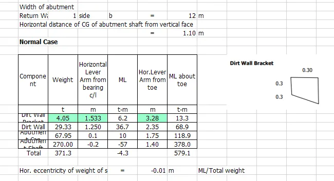
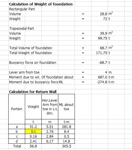
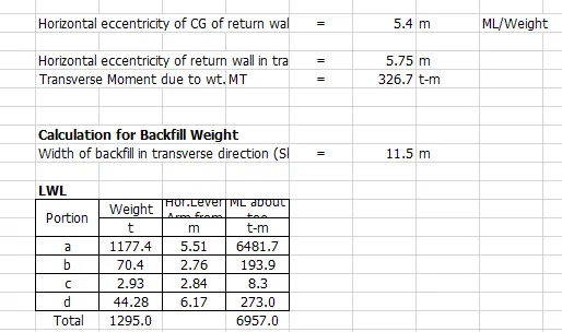
Calculation of loads of superstructure & substructure for pile as per given data
. 
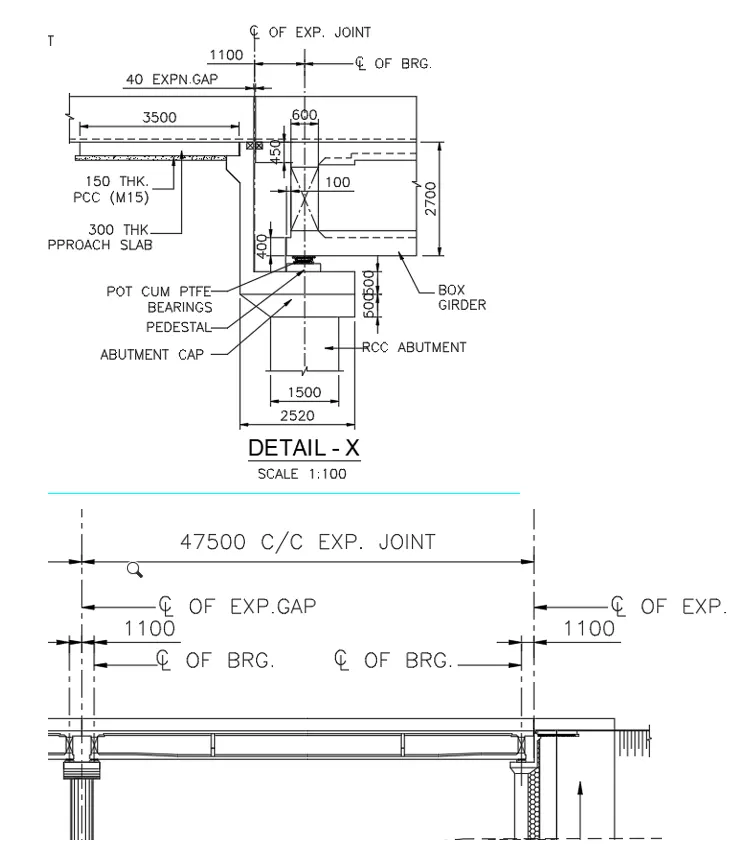
Data marked in red are given rest all are assumed
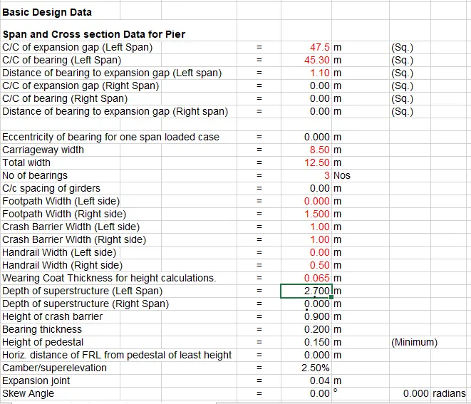
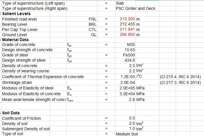


Report:
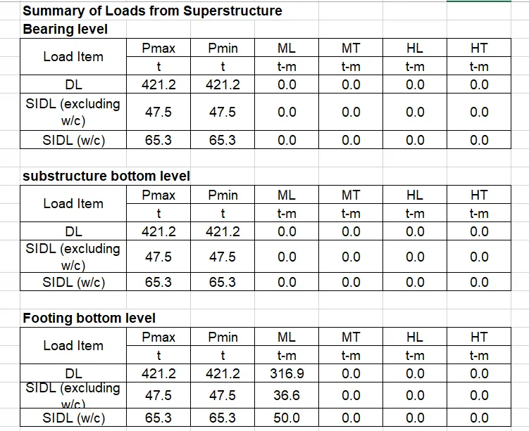
Summary of forces for design of pile foundation
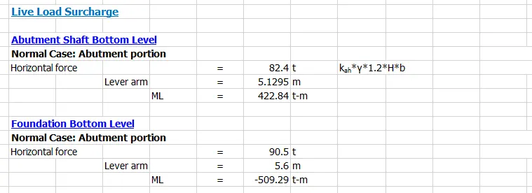
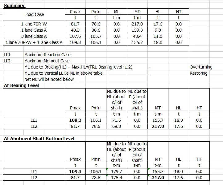
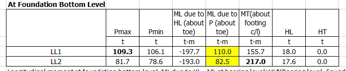
Summary of Live load
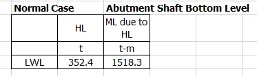
Summary of Earth pressure
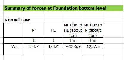
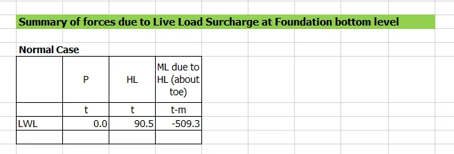
Summary of Abutment loading
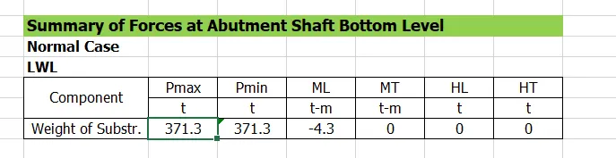
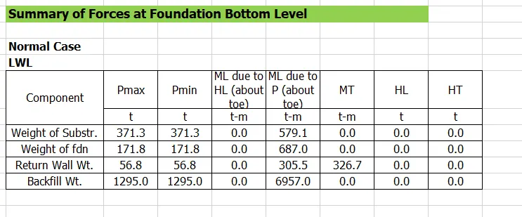
Excel of above calculations is attached herewith