Week 8 - Challenge 3 - Switch Bezel Design
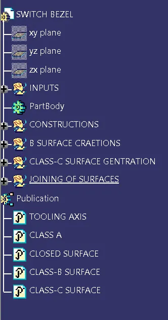
- Tree sturcture of the surface which is in simplified view.
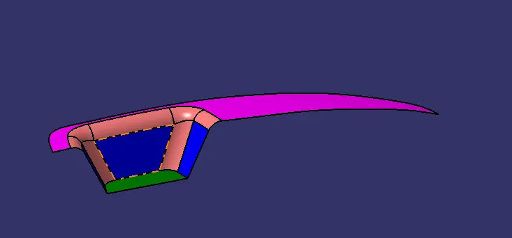
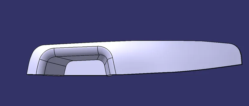
- Class-A surface provided by surface Engineer .
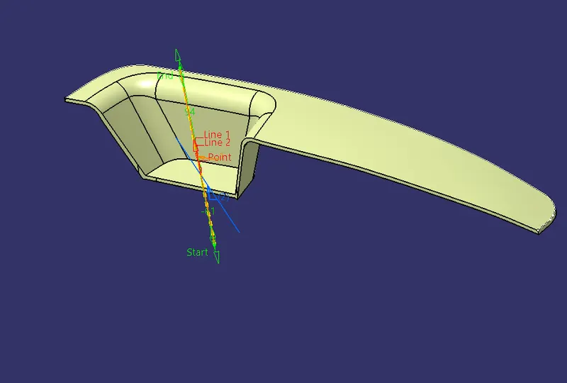
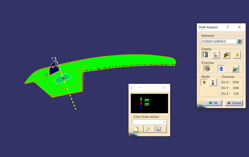
- Tooling direction is decided based on draft analysis on class-A surface, before draft analysis a dummy tooling axis is created, later selecting the faces which are presumed to have a draft less than ‘Three degree’ is selected and taking appropriate intersection and the Main tooling direction is created.
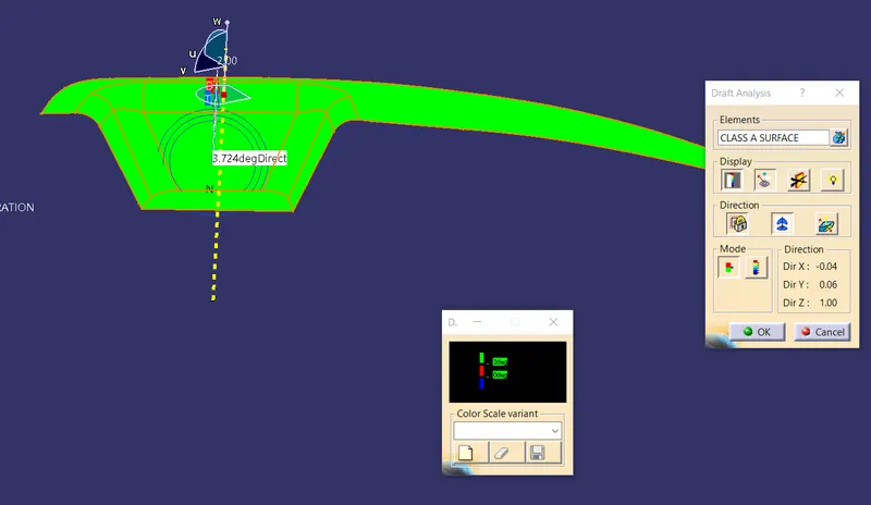
- A detailed draft analyis performed on the class-A surface to decide the tooling axis.
- Front view
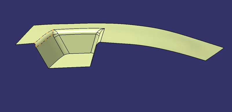
- Creation of Class-B surface by Class-A inputs.
- Front view of draft analysis on closed surface (includeing Class-A, Class-B and Class-c)
- Closed surface trimmed in an order of (Class-A with Class-C and combination is trimmed with Class-B)
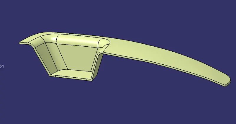
- solid part is created after draft analysis, part is prepared for injection moulding considering draft angle, manufacturability with respect to mould cavity and core.
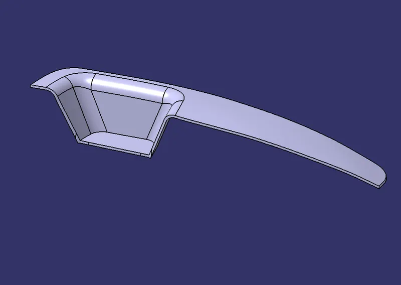
- Top view of solid part
Draft analysis is performed on the models to ensure a proper ejection of part from mold core, draft analysis is essential for any part which is to be manufactured in injection molding, draft angle for part should be a minimum of 3 degree, during the cooling process parts trends to adhere to the core and forcefully removing the part causes draw lines, wear and tear to mold cavity ,core and part itself.
Draft angle is provided on both core and cavity, conversely parts manufactures with less draft angle are more expensive when compared with higher draft angles.
Tooling axis ascertains the direction of mold cavity both for forward and withdraw form the core. To remove the part easily from core all part are given with draft angle, draft angle is analyzed in draft analysis by ‘analysis under the running point’ option.
Creating tooling axis for a simple part is easy, where as for a complicated part(parts containing contours, ribs and taper angles), many parameters needs to taken care.