Week 8 - Challenge 3 - Switch Bezel Design
STEP 1: CONNECTIVITY OF CLASS-A SURFACE
- First check the connectivity of the given surface or component
- This is done by creating boundaries or by using Join command
- Ensure that there is no gap between surface connection

- From this image we can see the boundary inside the surface, it indicates there is a gap.
- To solve this gap, use join option to merging the gap (use merging value as 0.003)

STEP 2: TOOLING AXIS CREATION
- First visually analyse the possible direction of Tooling direction.
- Create dummy tooling axis for possible dolling direction.
- Using the Intersection command create intersection line for all X,Y,Z axis direction.
Inter section of Y direction:

Inter section of X direction:
- If we have a surface with one sided wall, then create a opposite wall with own.
- Make angle contraint for this line with wall.

- Bisecting these X,Y directions tooling axis, the main tooling axis will create, Where the two lines and one point will be selected as inputs


STEP 3: B-SURFACE CREATION
- B-surface creation is done by offsetting class-A surface to required thickness.
- Offsetting class-A surface with fillets are more complicated, so go with extract and untrim the surfaces.
- Extract the all the sketch or surfaces used to create object and Untrim it.

Untrim:

- Extrapolate the surfaces till interact each relative surfaces.


- OFFSET it into required thickness of part
- Trim the surfaces to get proper surface without fillets, then fillet it.


FILLET

STEP 4: CLASS-C CREATION
- Create the boundary around the given Class-A surface.
- If this boundary has more surface, then split it into two or more boundary around the surface.


- Here the boundary has lots of intermidiate joints, this create gap while sweeping.
- To clear this joint make smoothening the curvaure.

- Now sweep the boundary with direction of tooling axis.
- This sweeping area is the thickness of the Class-C surface.

- Make extrapolate the sweep area to attain the intract with Class-A and Class-B surface if required.
- Do trim operation sweep area with both class-A&B surfaces.


After done Trimming operation the finel Class-C surface created.

- For make it solid use close command on Part workbench

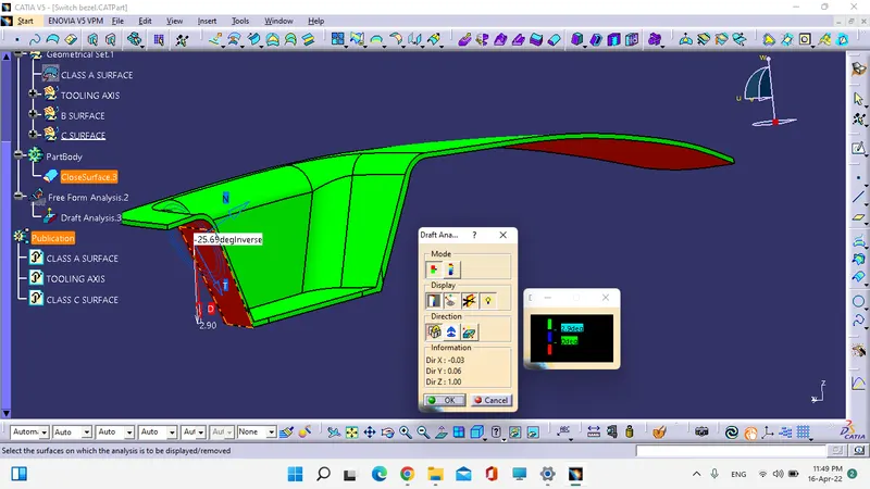
STEP 5: DRAFT ANALYSIS
- Draft analysis is done after determine the tooling axis.
- Ensure weather all the surface angles are more than 3 degrees along with tooling axis direction.
- There are some colour codes are used to easily determine the angle value

- If the whole angle is more than 3 degrees, then surface colour turned into Green for one type scale and for another scale it has 5 colour variation.
- Here our surface area has more than 3 degrees.

- Below 0° angle indicated by red in colour, these are has negative angles.
STEP 6: PUBLICATION
- Create publication for Tooling axis, Draft analysis and B&C-surface creation

TOP, FRONT, SIDE & ISOMETRIC VIEW OF AN CLASS-C SURFACE:
