Week 8 - Challenge 3 - Switch Bezel Design
Aim:
To thicken the given Switch Bezel plastic component along with the draft analysis.
Procedure:
The tooling direction is given for the movement of the machine which needs to open after the moulding operation. In other words it is said that after the moulding operation the piece in the cavity has to be removed and need to be removed in the direction for that purpose the tooling direction is used.
Creation:
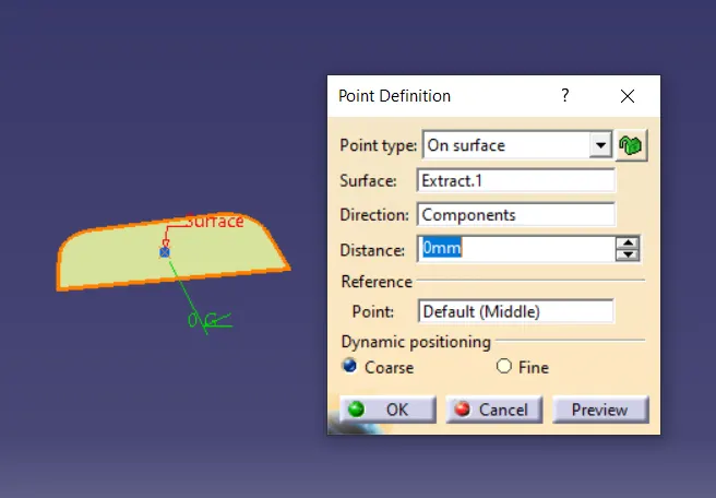
Before creating the axis the bottom surface of the switch bezel is extracted as in the image after that an point is created at the centre with the distance as 0mm. And after that axis is created along the centre point.
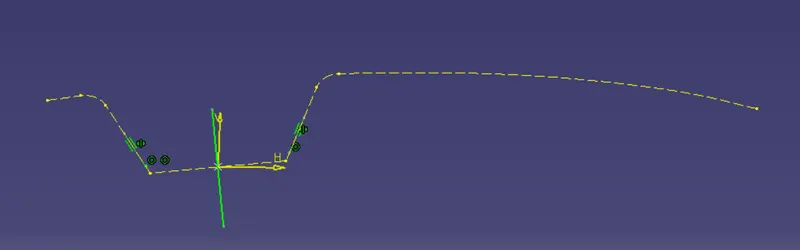
After creating the centre point go to the sketch with the selecting the axis as yz axis. After going into the sketch select the surface A and intersect the line creates as in the image afer that draw two lines make sure that it is tangency.
After creating the two lines again go to the line option and change the line type as bisect and select the two line click ok creates an line.
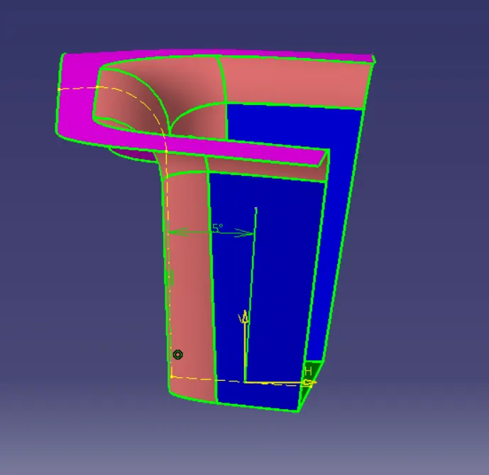
After creating the centre point go to the sketch with the selecting the axis as xz axis. After going into the sketch select the surface A and intersect the line creates as in the image afer that draw two lines make sure that it is tangency and draw another and constrain the two line with the respective distance.
After creating the two lines again go to the line option and change the line type as bisect and select the two line click ok creates an line.
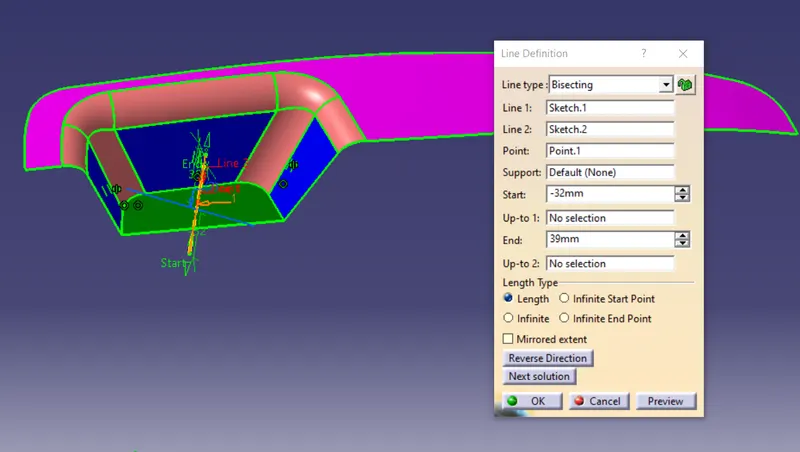
After that select the two lines created with the centre point and click ok another line creates which is the main tooling axis.
Creating B surface
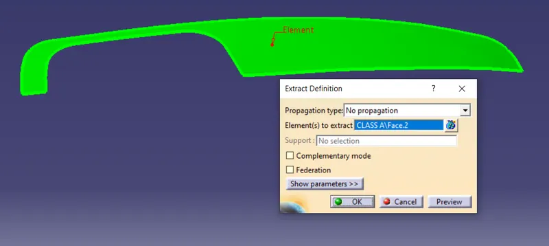
Now select the top surface i.e., bezel armrest and extract the surface. After extracting the surface untrim the extracted surface and offset the untrimmed surface to the respective direction.
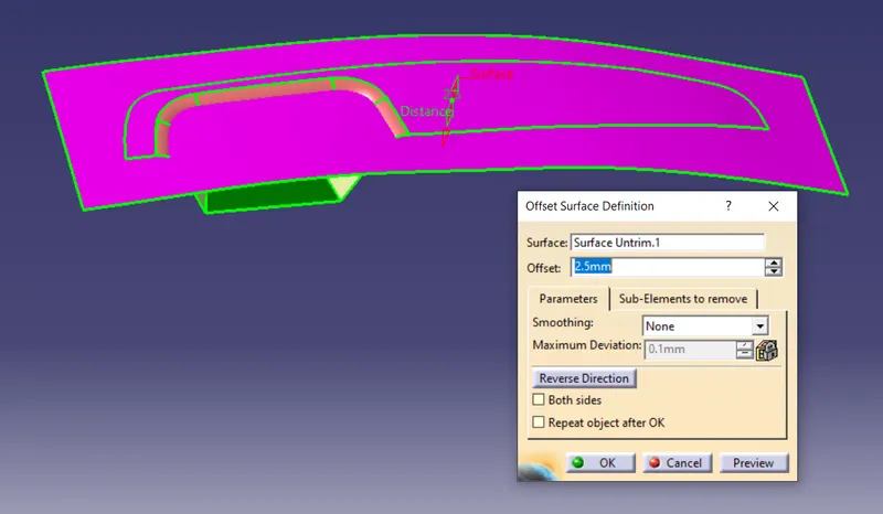
Now select the walls of the 3 sides and extract individually. After that untrim all the wall and extrapolate the walls. After that offset the wall and trim all the 3 walls.
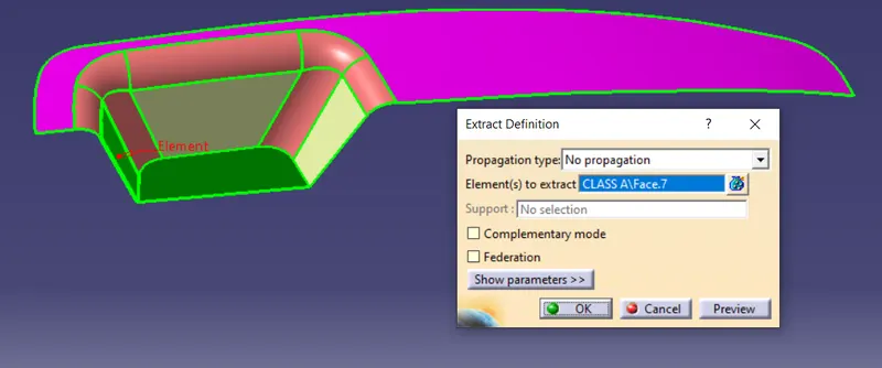
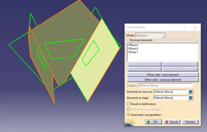
Now extract the bottom part and untrim the surface and extrapolate it.
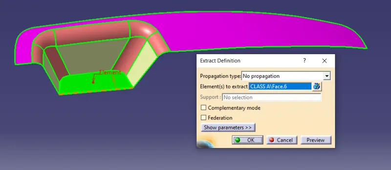
After offseting the all the surface trim the surface as the class A. After trimming the base part to the top and trimming all the top and wall part to the bottom part. Gets the final part of the class B surface.
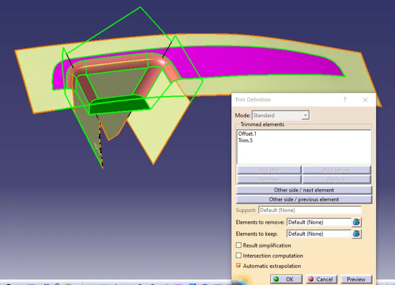
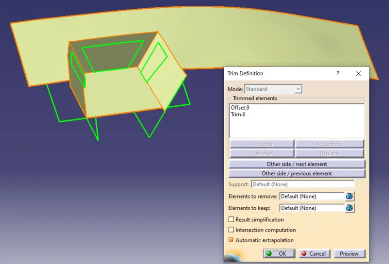
For the fillet part select one side of the fillet region extract it and untrim. After that measure the fillet region. Now by using the edge fillet calculate the fillet radius and the thickness so that the edge will be filleted.
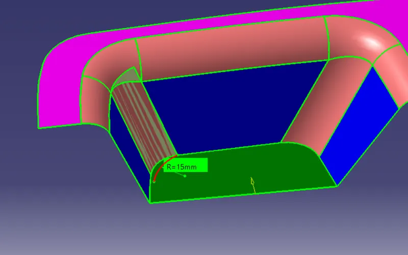
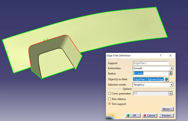
After the edge fillet.
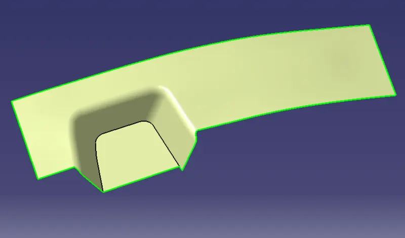
Creating class C surface
Before the class C there are some operation need to be done for that we need to make the boundary of the class A surface. Two different part is selected for the boundary for that click the boundary option and propagation type is point continunity and select the line as the image and click ok and select the other side as the same way.
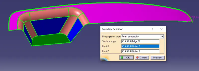
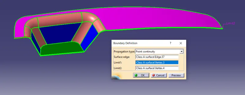
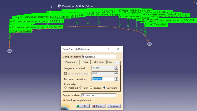
Now the boundary is created on the both the side. We can see there will be some patches in the boundary created, for that select the curve smooth option and select the line select the curvature and click ok now the boundary line gets smoothed.
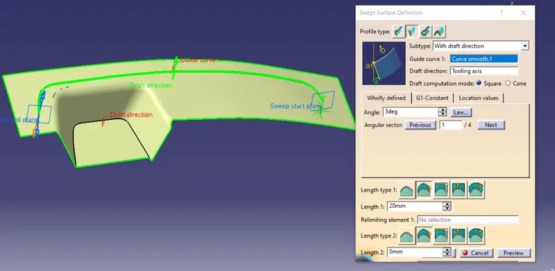
After that for creating the class c surface go to the sweep option select the second option and subtype into with draft direction and click ok. Like the same way the other side is also done.
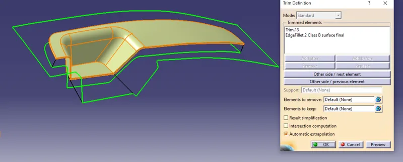
At the edge there will be some line is will be not connected for that extrapolate the line on the both sides and trim the surface. Now join the sweep which is created. and trim the class B surface with the class C surface.
Draft Analysis
Draft analysis is required to check if a part has required draft or not. Draft is required so that a part can be ejected from its mould.
Click on the draft option and click on the compass and make the compass set on the tooling axis. After that there will be red cross mark click on the part and show the green which will the pass for the manufacturing or if it shows any other color the work has to be redone with the tooling axis.
With the analyses under running point check the thickness which is same under all the parts
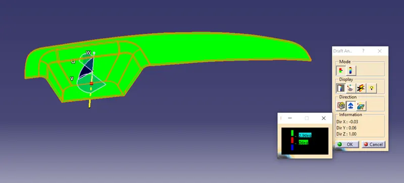
The Final Output
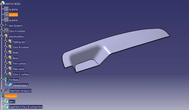
Result:
With the given thickness the class B and C is formed along with the draft analysis the part is passed for further operation.