Week 8 - Challenge 3 - Switch Bezel Design
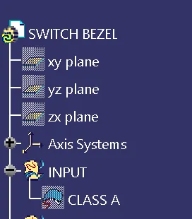
INPUT
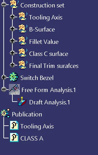
SURFACE CONSTRUCTION SET
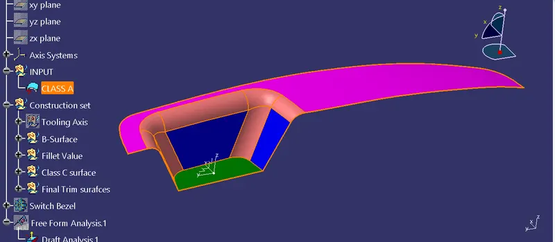
A-CLASS SURFACE
Tooling axis creation
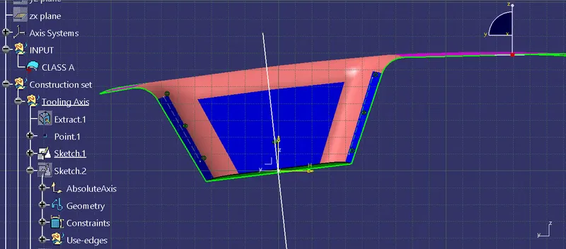
1) Y-AXIS TOOLING AXIS
we need to project the component 2D on the sketch(yx plane) and through the tangent line along the profile line, we will draw a bisecting line as shown below which will be the tooling axis in Y-direction.
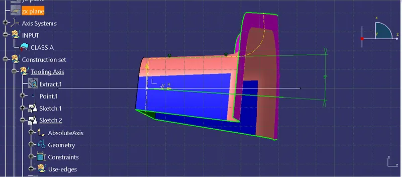
2) X-AXIS TOOLING AXIS
we need to project the component 2D on the sketch(xz plane) and through the tangent line along the profile line and a normal line at 3-degree draft inclination. we will draw a bisecting line as shown below which will be the tooling axis in x-direction.
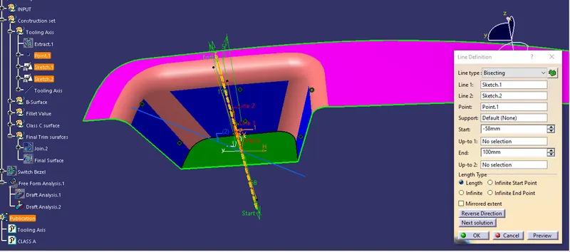
3) MAIN TOOLING AXIS
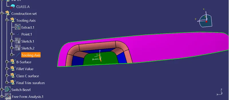
Furthur we will bisect the X and Y tooling axis to get the main tooling axis.
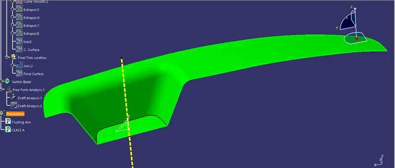
DRAFT ANALYSIS FOR A-CLASS SURFACE
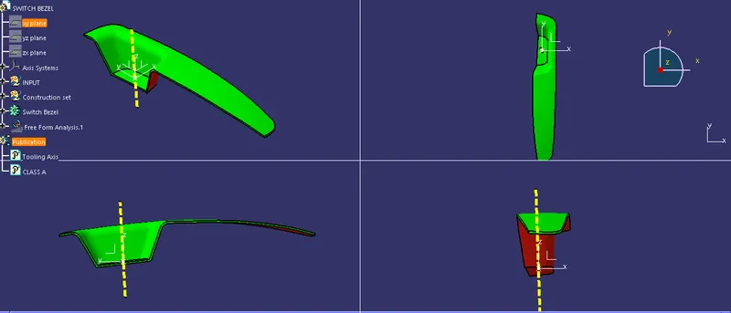
The green shaded portion signifies the clearance surface for the given draft of 2.9 degree
in order to do so
- set the compass for the draft analysis aligned to the tooling axis
- The lock the compass and set the parameter for the draft
- click the part body or surface for draft analysis
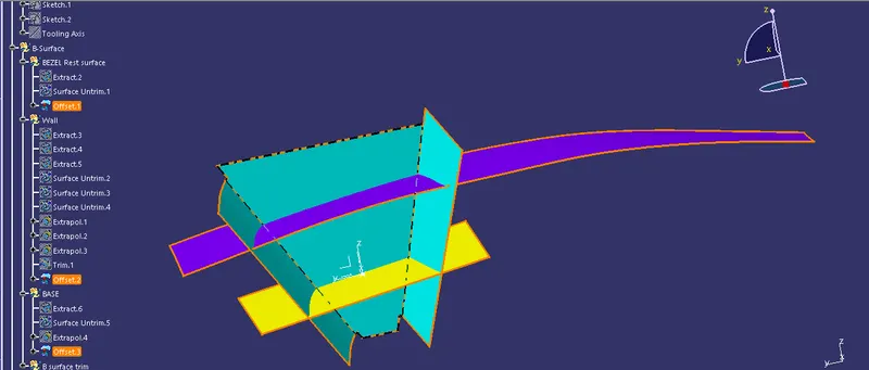
B-CLASS SURFACE EXTRPOLATED OFFSET SURFACE
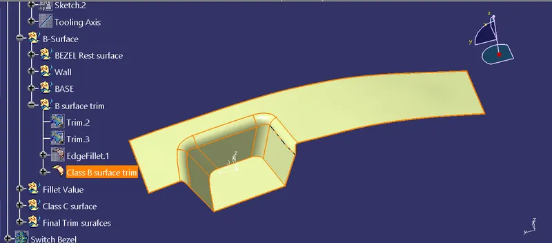
B-CLASS SURFACE
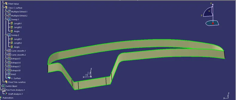
C-CLASS SURAFCE
(A+C) JOINED SURFACE
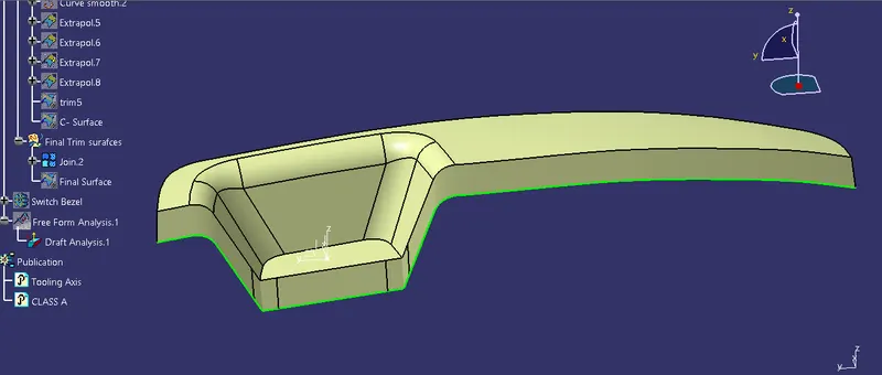
FINAL TRIMMED CLOSED SURFACE
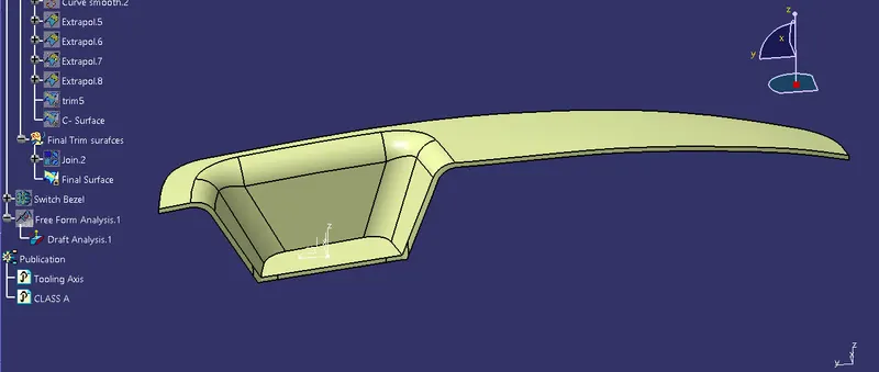
SOLID CLOSED PART BODY
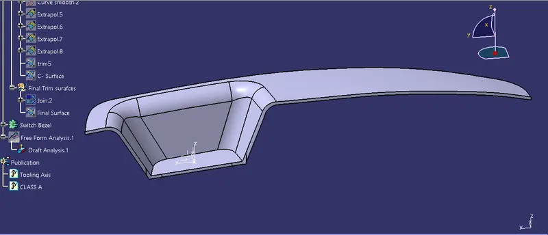
COMPARSION WITH INPUT A-CLASS SURFACE
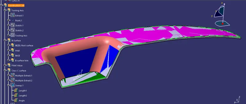
DRAFT ANALYSIS FOR CLOSED PART
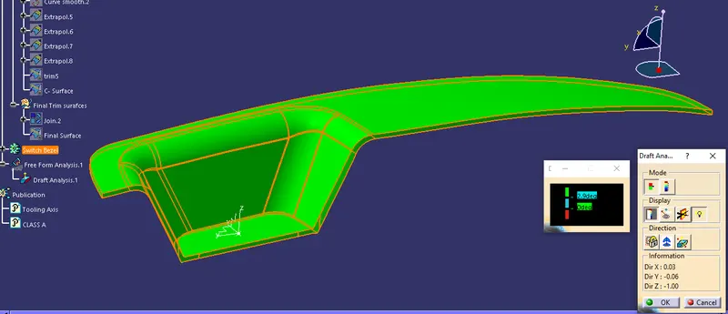
Draft angle in various orientations