Week 8 - Challenge 3 - Switch Bezel Design
Aim:
To create the final product from a given Switch Bezel Class A surface and perform Draft analysis on the Class A and also on the Switch Bezel.
Theory:
Draft Analysis:
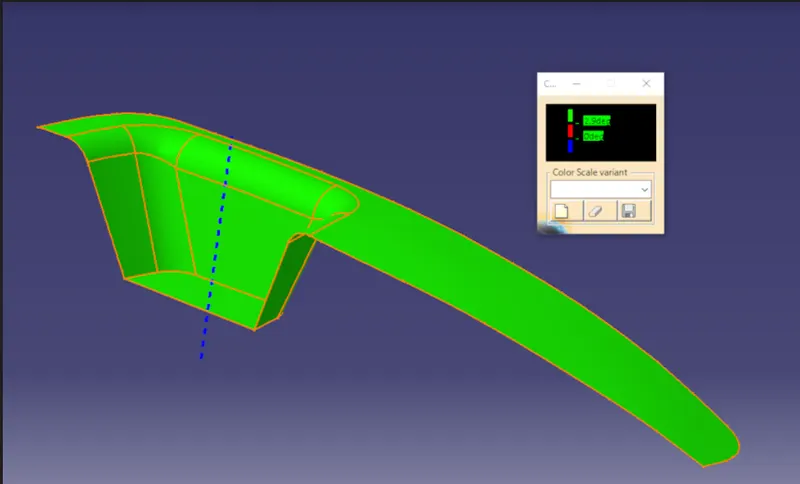
Draft Analysis is performed to check the manufacturability of the product.In Draft Analysis, the Class C surface i.e.side walls are checked for draft. A minimum if 3 degrees draft is expected on the component to make it manufacturable without any damage to the product. The tooling axis of the product depends on the Draft analysis. Most of the component is deemed to clear in the Tooling axis,if any part in case can be cleared using Side core.
Class A Surface:
Class A surface is the surface which is visible to the naked eye and has it job of being completely aesthetic.Class A surface are generated using tool like Alias.
Class B Surface:
Class B surface is the one which is present of the other side of the part and is completely hidden from naked eye view. It is where the various B side features such as Ribs,Dog houses and screw bosses are made.
Class C Surface:
Class C surface is the one which joins Class A and Class B. It is the created with a draft to the tooling axis.The draft also made keeping in mind Parting line. The parting line is supposed to be on the Class B surface
Procedure:
- Creating Tooling Axis using Bisecting method:
Tooling Axis is created using the Intersection method. At first the clearnace of the cavity is checked manually in all the possible direction. It is concluded that the z axis is the most feasable direction for tooling axis. So the X and Y axis are projected on the part using the "Intersection" command.
X axis tooling clearing is checked by making a bisecting line from two lines drawn in the z direction.The bisecting line clears the X axis.
Y axis tooling clearing is checked by making a bisecting line from two lines drawn in the z direction.The bisecting line clears the Y axis.
A final Tooling Axis is made by bisecting the X and Y direction clearing axes.This line gives the direction of moving of Cavity Die.
- Class B Surface:
Class B surface is generated using the Class A surface by extracting,offsetting,extrapolating and trimming the adjacent surfaces part by pat. The whole component is divided into smaller parts and the above stated procedure is repeated for every part,until the complete Class B surface of the product is modelled.
- Class C Surface:
Class C surface is designed keeping in mind the Tolling axis. It is designed with a 3 degree draft with resoect to the Tooling axis in order to properly eject the part without any damage while manufacturing.The draft also made keeping in mind Parting line. The parting line is supposed to be on the Class B surface.The entire boundary is divided and is swept along the Draft angle and direction across the part.
- Solid component:
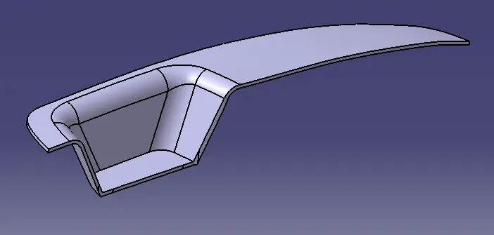
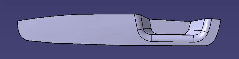
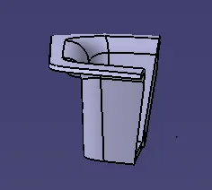
The Class A,Class B and Class C surface are joined together using the Join command or Trim command making it a closed body. The Part workbench is then opened and the closed body is converted to a Solid Component. Later,Draft Analysis is performed on it.
- Draft Analysis:
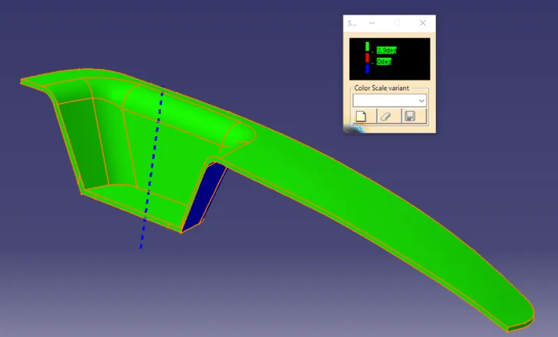
Draft Analysis is performed using the Draft analysis command. The Universal compass is fixed on the Tooling axis and the part is selected. The values of Draft are fed to get different color codes and a thorough inspection is done all over the part.
Observation:
The areas in Green colour will clear the Tooling axis with the required draft,making the part manufacturable.
Conclusion:
The Draft Analysis of a Switch Bezel is succesfully performed and the Tooling Axis is made.