Week 8 - Challenge 3 - Switch Bezel Design
SWITCH BEZEL:
OBJECTIVE:
To create the Switch Bezel Plastic component through the given Class-A surface. To begin with, the tooling axis for the given Class-A Surface should be created meeting the requirements of the draft angle and at the end perform the Draft analysis on the model.
1.INPUT SURFACE:
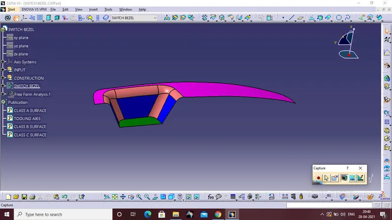
GIVEN CLASS A SURCAE
2.TOOLING AXIS:
First step is to create the tooling axis of the given class A surface,
1.For craeting tooling axis extract the base surface of the given class A surface.
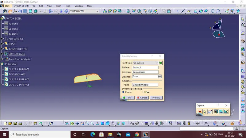
2.Then create the point on the extract surface.
3.After that create the axis system on the point.
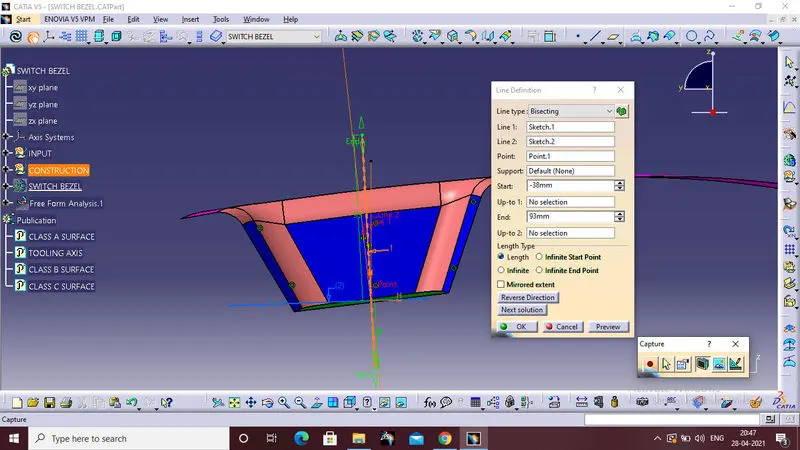
4.Then use the sketch option and create the tooling axis by using bisecting line method.
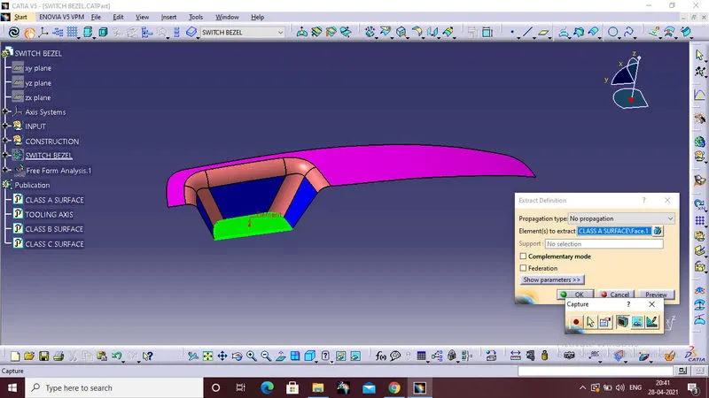
Tooling in Y direction

Tooling in X direction
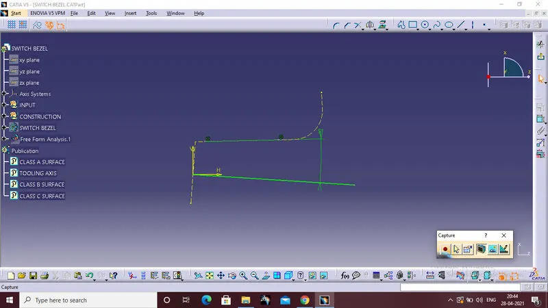
To bisect the tooling x direction and tooling in y direction at the center point to get the main tooling axis.
3.CLASS B SURFACE:
1.Bezal rest surface
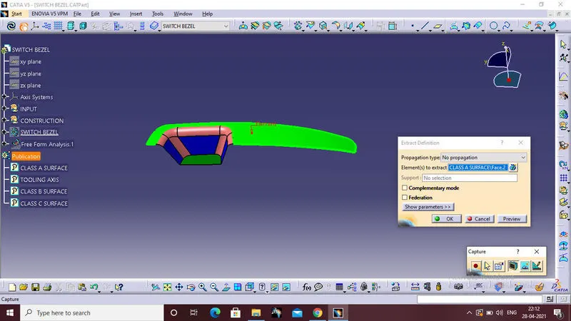
First part of the class B surface is an bezal rest surface,for bezal surface first extract the top surface of the class A surface.
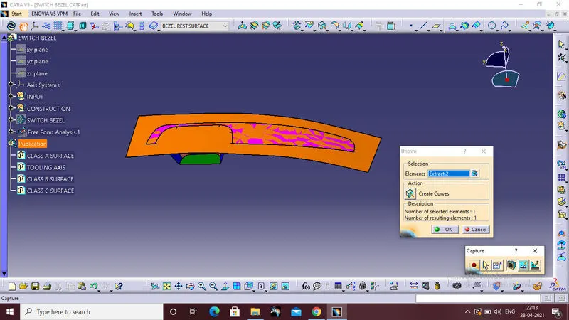
untrim the extract surface to get the proper shape
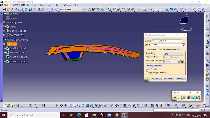
Next step is to offset the untrim surface at 2.5mm.Because the wallthickness of the component is 2.5mm.
2.WALLS:
Second part of the class b surface is walls,to create the walls first step is to extract the inside three verticle surfaces.
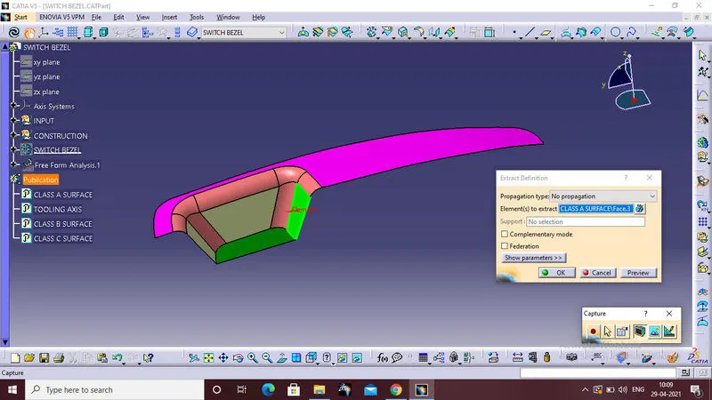
Then untrim the extract surface to achieve the proper shape
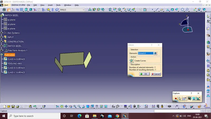 Then extrapolate the untrim surfaces for completely intersect with each others.
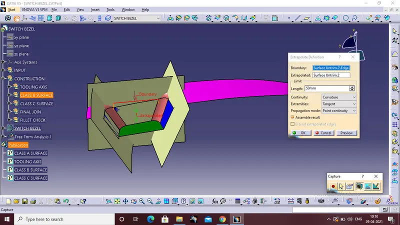
Next step is to trim the extrapolated surfaces.
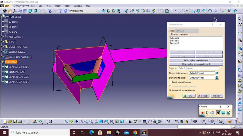
Then offset the trim surface in to 2.5mm.
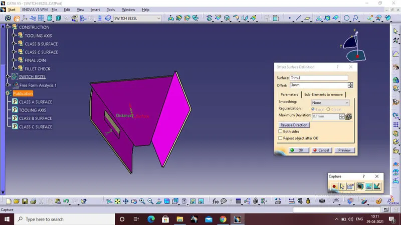 3.BASE:
The next part of the class B surface is base,for base surface first extract the base surface of the class A surface.
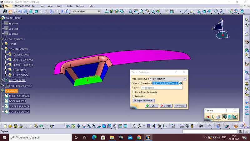
untrim the extracted surface to get the proper shape.
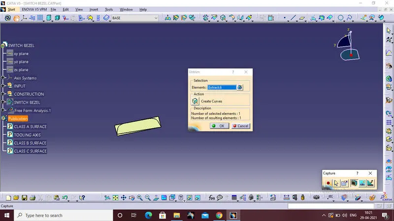
Extrapolate the untrom surface to completely intersect with each other.
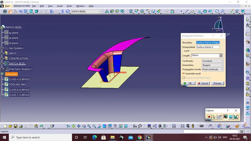
Offset the extrapolated surface in to 2.5mm to the downward direction.
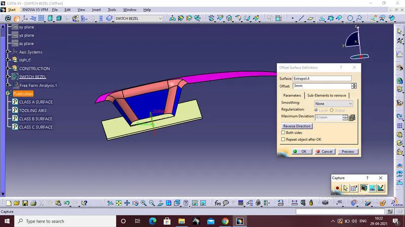
4.FINAL TRIM CLASS B SURFACE
Finally to trim the offested surface with each other properly by using trim command.this surface is the our required class B surface.
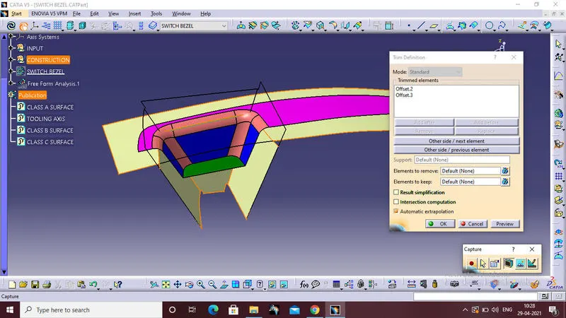
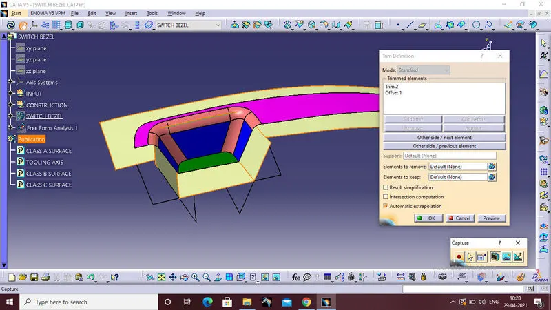
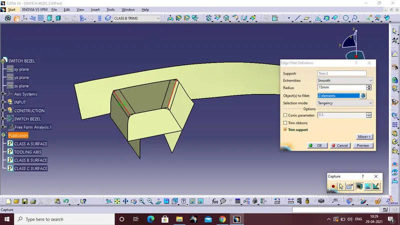
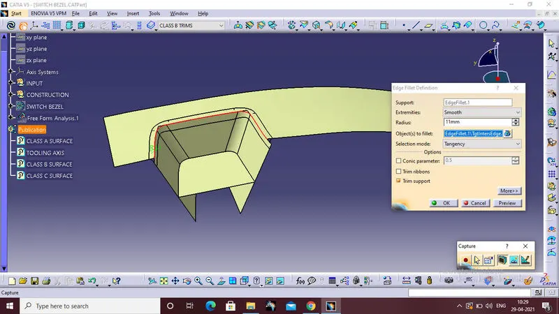 FINAL CLASS B SURFCAE
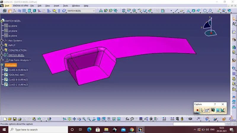
4. CLASS C SURFACE:
For class c surface creation,first step is to extract the outer profile of the class a surface.
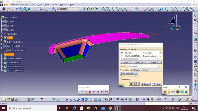
Next step is to swep the extracted curves by using swept command
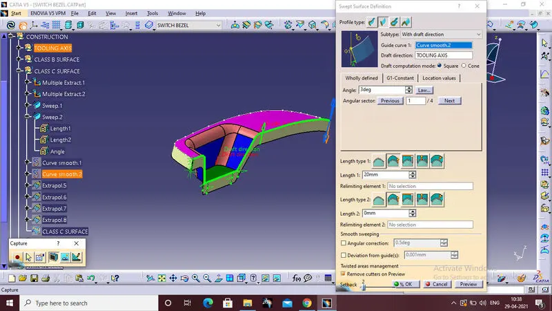
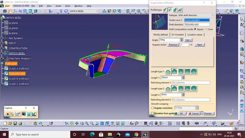
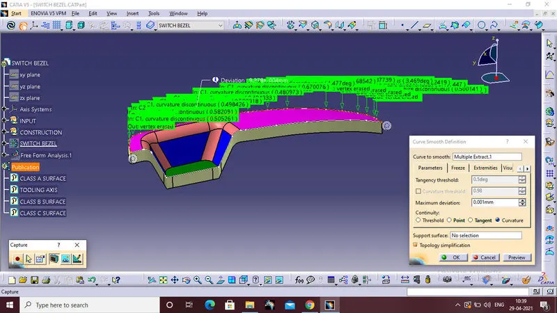
To smooth the swpet surface to get the better surface finish use the smooth curve option.
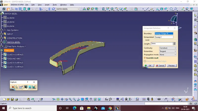
Then extrapolated the swept surfaces to get the complete intersection with each other parts.
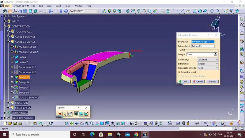
Than finally trim the extrapolated surfaces with each other to got the final c surface.
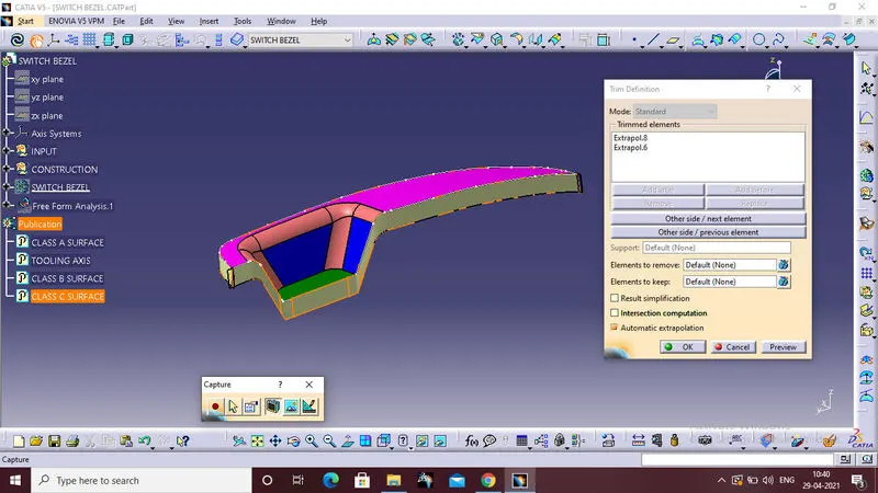
CLASS C SURFACE:
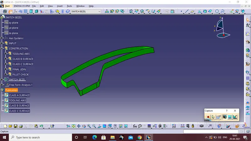
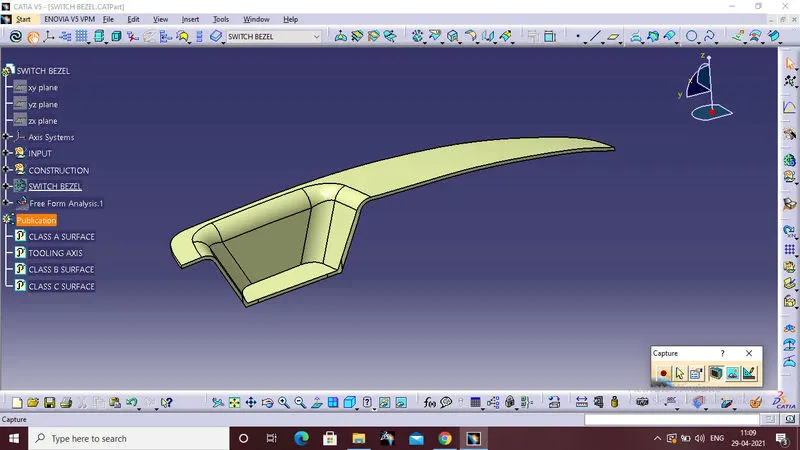
5.FINAL JOIN SURFACE:
To craete the final surface trim the extrapolated surface of calss a and the class c surface first.
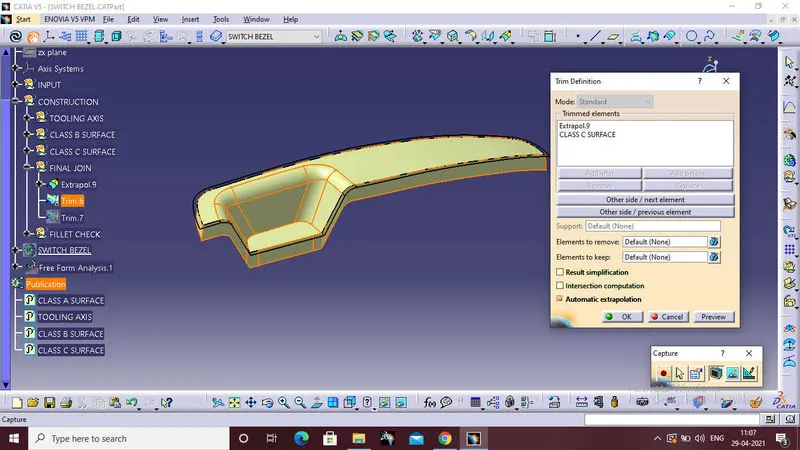
Than trim the last trim surface and class B surface, the final output of the trim surface is the our final trim join surface.
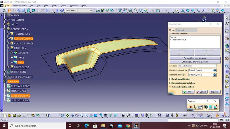
Final trim surface:
5.SOLID BODY:
To create the solid body of the trim surface ,first select the part workbench from the part workbench select the command closed surface and select the wallthcikness of the component 2.5mm.
This is the final solid body of the trim component.
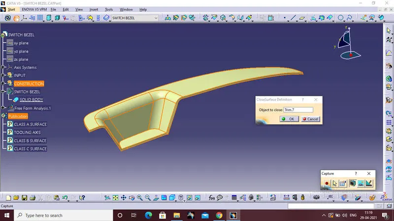
final solid body
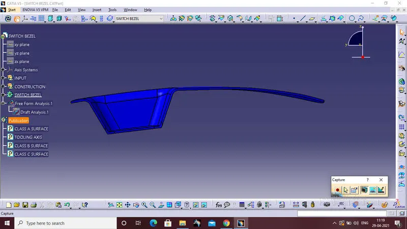 6.DRAFT ANALYSIS:
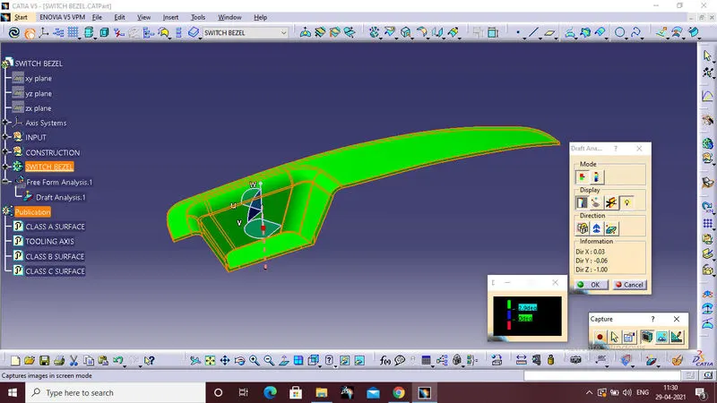
The Draft Analysis command enables you to detect if the part you drafted will be easily removed. This type of analysis is performed based on color ranges identifying zones on the analyzed element where the deviation from the draft direction at any point, corresponds to specified values.
PROCEDURE:
- enter part in Catia.
- Go to Material Mode.
- 03.go for draft analysis.
- drag axis bar to the tooling direction of part.
- check for draft and make parting line as per analysis
7.PUBLICATION:
Publications allow you to modify a model without invalidating the features defined in the analysis document. If you modify the entity to which a publication refers in a CATIA V5 part or assembly, all of the features in the analysis document using that publication are updated to refer to the new entity.
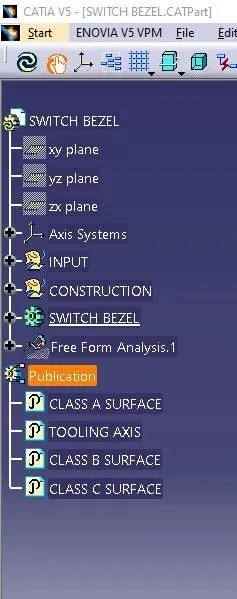
Publish the class A and class B and class C surface along with the tooling axis.
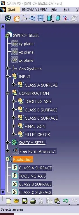
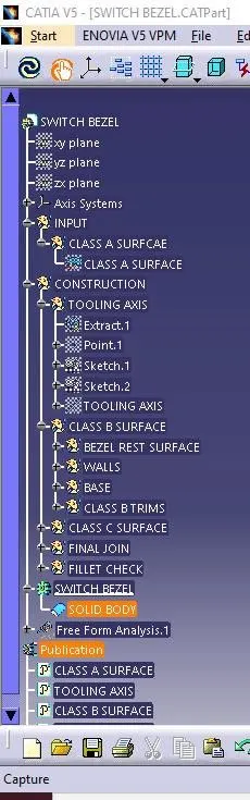
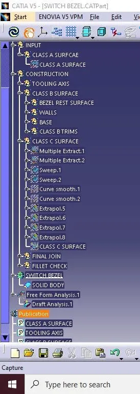
Tree structure:
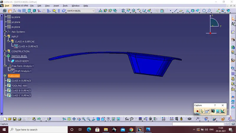
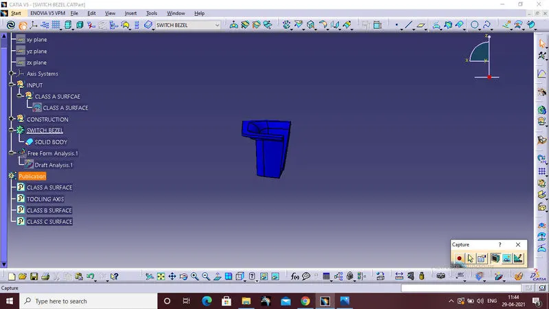
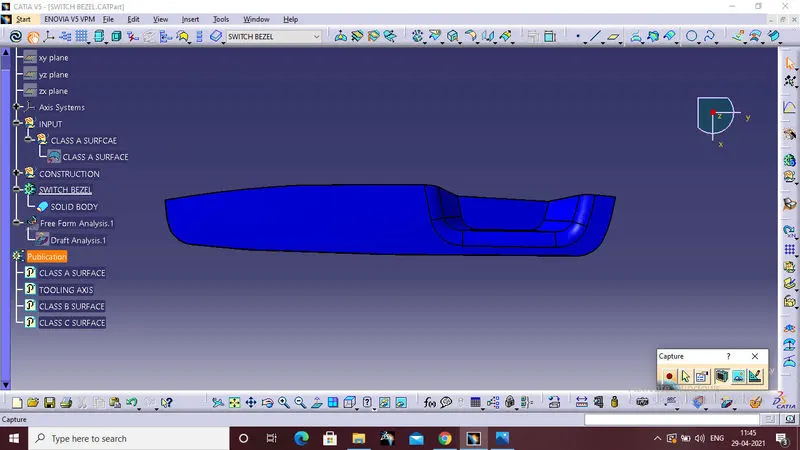
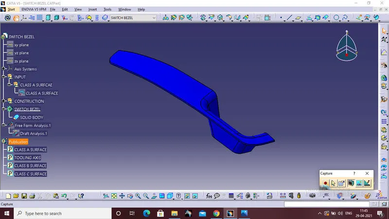
VIEWS:
FRONT VIEW:
SIDE VIEW:
TOP VIEW:
ISOMETRIC VIEW:
RESULT:
The creatation of the the Switch Bezel Plastic component through the given Class-A surface. And the tooling axis for the given Class-A Surface should created meeting the requirements of the draft angle and at the end perform the Draft analysis on the model to be sucessfully completed by using catia software.