Week 8 - Challenge 3 - Coin Holder Design
Week 8 - Challenge 3 - Coin Holder Design
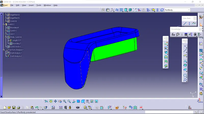
AIM:- TO Create the Coin Holder Plastic component through the given Class-A surface. To begin with, the tooling axis for the given Class-A Surface should be created meeting the requirements of the draft angle and at the end perform the Draft analysis on the model.
Draft Analysis ?
The Draft Analysis allows the user to easily analyze a part for proper draft angle. A Draft Angle describes the amount of taper for molded or cast parts perpendicular to the parting line.
Draft angles ?
Draft angles are very important in thermoforming product design. If the product is formed onto a female or negative mold, it shrinks away from the mold sidewalls. As a result, true female or negative products can be thermoformed with vertical walls having zero draft angles. If the product is formed onto a male or positive mold, it shrinks onto the mold sidewalls. A draft angle of 1–5 degrees is recommended for all male or positive products.
here we are taking minimum 7degree of draft angle because our die should not get damage and we should get a finish good product. In some area we cannot avoid negative draft. So bending operation is provided for the manufacturing process, because deep drawing cannot be done at the negative draft area.
Tooling Direction for Plastic Part
Tooling direction is main consideration for plastic part and mold parts because it defines movement of mold part and possibility of plastic part to come-out from mold part (Core and Cavity).
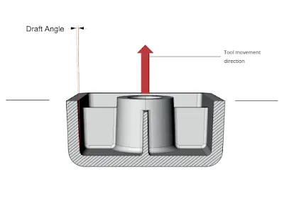
Tooling Direction:-
In Molding machine arrangement is given to open the mold along a direction which is known as Tooling Direction.
In other words. The mold is built from two separate halves (Core and Cavity) and tooling direction basically define the direction of mold pulls apart.
Tooling direction is known as primary direction.
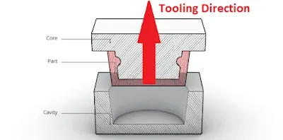
WHAT IS CLASS A, B, C SURFACES ?
Class A:- Styling or A class surface are the terms used in plastic product design. That means the surface of a component that is smooth (aesthetic) or visible side to the human eye after the part is assembled.
Class B:- It is an engineering surface, and it gives you thickness from class A surface
Class C:- when Class A and Class B surfaces are joined along the tooling axis it is called class C surface.
CREATION OF TOOLING AXIS
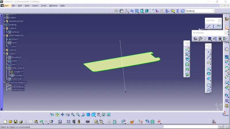
DRAFT ANALYSIS FOR CLASS A
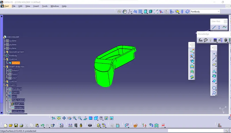
CREATION OF CLASS B SURFACE
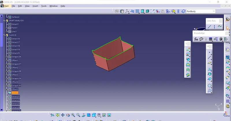
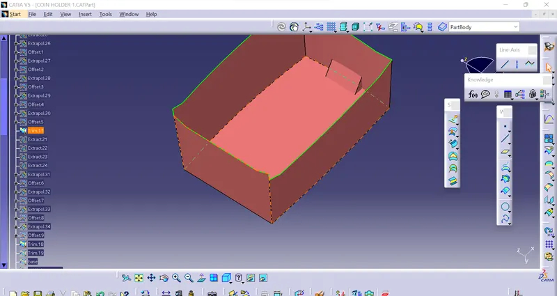
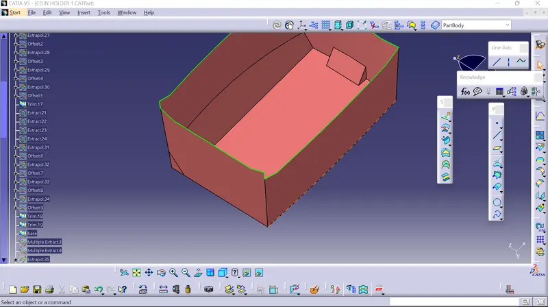
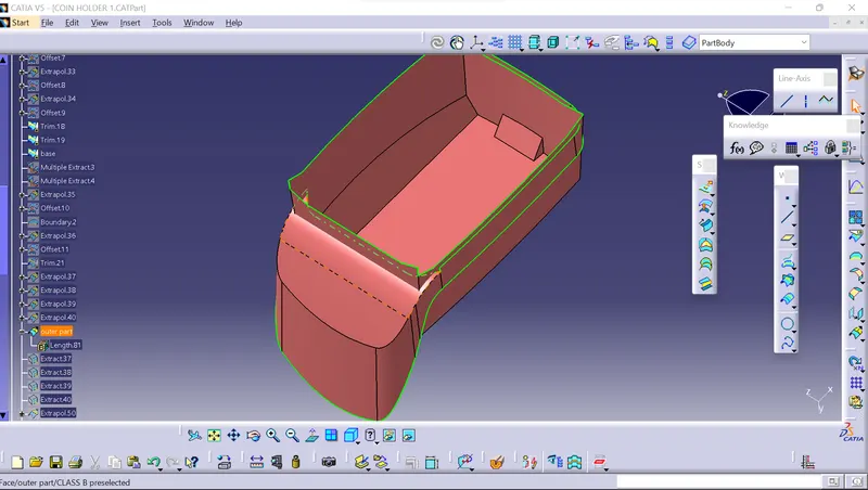
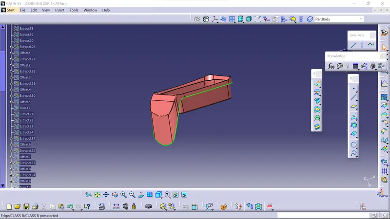
CLASS A+B+C
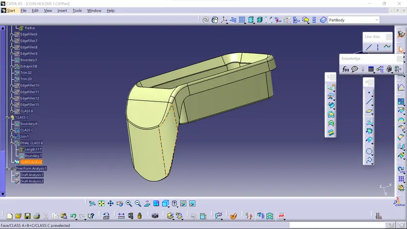
CREATION OF CLOSED SURFACE
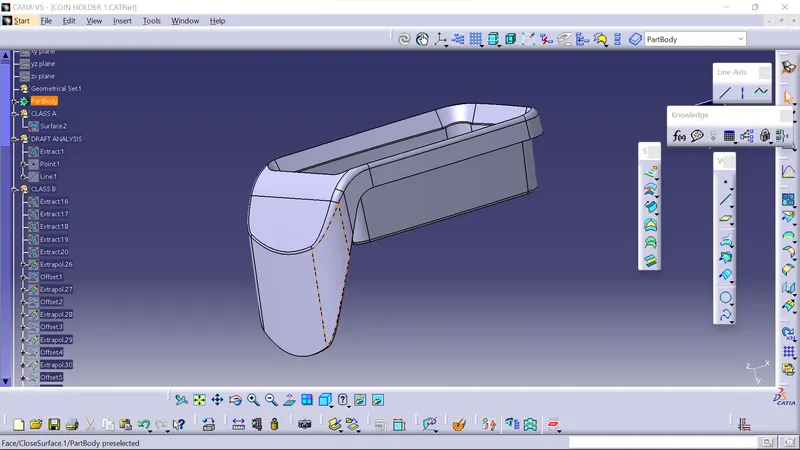
FINAL DRAFT ANALYSIS